sexual manual

Sexual health is a central aspect of being human, encompassing pleasure, intimacy, and reproduction throughout life; it’s fundamentally linked to overall well-being.

Comprehensive sexual education provides accurate, age-appropriate information crucial for health and survival, acknowledging the reasons people engage in sexual activity.

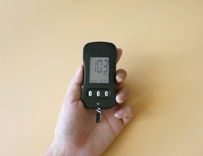
Safe sex practices decrease body fluid exchange, minimizing STI risk during oral, vaginal, and anal sex, requiring open communication with partners beforehand.

Today is 12/10/2025 23:06:48 ()

Defining Sexual Health: A Holistic View

Sexual health extends far beyond the mere absence of disease or infirmity; it represents a state of complete well-being in all matters relating to sexuality.

This holistic perspective, as highlighted by recent understandings, necessitates a broad consideration of sexuality itself – a central aspect of human existence throughout the lifespan.

Sexuality encompasses sex, gender identities and roles, sexual orientation, eroticism, pleasure, intimacy, and reproduction, all interwoven and influencing behaviors and outcomes related to sexual health.

It’s not simply about physical function, but also about emotional, mental, and social well-being.

A truly holistic view acknowledges that sexual health is influenced by individual values, beliefs, and experiences, as well as broader societal and cultural contexts.

Understanding this interconnectedness is vital for promoting positive sexual health outcomes and fostering a respectful and inclusive approach to sexuality.

Ultimately, defining sexual health holistically empowers individuals to embrace their sexuality as a natural and healthy part of being human.

The Importance of Comprehensive Sexual Education

Comprehensive Sexuality Education (CSE) is critically important, providing young people with accurate, age-appropriate information about sexuality and their reproductive health – essential for their overall health and survival.

Unlike limited approaches, CSE doesn’t just focus on abstinence; it equips individuals with the knowledge and skills to make informed decisions about their sexual lives.

This includes understanding consent, healthy relationships, contraception, sexually transmitted infections (STIs), and sexual pleasure.

Developed through collaborative efforts by UNESCO, UNFPA, UNICEF, UN Women, UNAIDS, and WHO, CSE programs are tailored to local contexts.

Recognizing why people engage in sexual activity is crucial, acknowledging that sexual experiences can and should be pleasurable, promoting safer practices.

CSE empowers individuals to navigate their sexuality responsibly, fostering respect for themselves and others, and reducing risks associated with unprotected sex.

Understanding Sexually Transmitted Infections (STIs)

STIs spread through body fluid exchange during sexual contact—oral, vaginal, or anal—necessitating open communication with partners about STI status and safe practices.

Common STIs: Symptoms and Prevention

Numerous STIs exist, each presenting unique challenges to sexual health. Recognizing symptoms is crucial for early detection and treatment, preventing further complications and transmission.

Common infections include chlamydia, gonorrhea, syphilis, herpes, and human papillomavirus (HPV). Symptoms vary widely, ranging from noticeable sores or discharge to often being asymptomatic, particularly in early stages.

Prevention strategies are paramount. Consistent and correct condom use significantly reduces transmission risk during vaginal, anal, and oral sex. Regular STI screenings are vital, especially for sexually active individuals with multiple partners.

Open communication with partners about sexual history and STI status is essential for informed decision-making and mutual protection. Vaccination is available for HPV and hepatitis B, offering proactive protection against these infections.

Early diagnosis and treatment are key to managing STIs effectively and preventing long-term health consequences. Ignoring symptoms can lead to severe complications, including infertility and chronic pain.

Safe Sex Practices: Minimizing Risk

Prioritizing safe sex is fundamental to protecting your sexual health and the health of your partners. This involves a multifaceted approach, encompassing behavioral choices and barrier methods.

Consistent condom use remains the cornerstone of STI prevention, significantly reducing the risk of transmission during vaginal, anal, and oral sexual encounters. Proper application and usage are crucial for effectiveness.

Reducing the number of sexual partners lowers your overall risk of exposure to STIs. Mutual monogamy, with prior STI testing for both individuals, offers a higher level of protection.

Open and honest communication with partners about sexual history, STI status, and boundaries is essential for informed consent and shared responsibility. Discussing safer sex practices beforehand fosters trust and respect;

Regular STI screenings are recommended, particularly for sexually active individuals, to detect and treat infections promptly, preventing further transmission and potential complications.

The Role of Communication with Partners

Effective communication forms the bedrock of any healthy sexual relationship, fostering trust, respect, and mutual understanding. It’s not merely about discussing logistics, but about openly expressing desires, boundaries, and concerns.

Honest conversations regarding sexual history and STI status are paramount before engaging in sexual activity. This transparency allows for informed decision-making and shared responsibility for sexual health.

Discussing safer sex practices – including condom use, testing schedules, and risk reduction strategies – demonstrates respect for both your well-being and your partner’s.

Expressing desires and boundaries clearly and respectfully ensures that all sexual encounters are consensual and enjoyable for everyone involved. Active listening and validation are key.

Regular check-ins about sexual satisfaction and any emerging concerns can strengthen the emotional connection and address potential issues before they escalate.

Contraception and Family Planning

Contraceptive methods empower individuals to control reproductive health, with options ranging from emergency contraception to long-term solutions, ensuring informed choices.

Plan B One-Step, while effective, requires backup methods and is a one-time use option after unprotected sex, not a consistent birth control solution.

Emergency Contraception: Options and Effectiveness

Emergency contraception (EC) offers a crucial safety net after unprotected sex or contraceptive failure, providing a chance to prevent unintended pregnancy. Primarily, Plan B One-Step is a widely recognized option, containing levonorgestrel, and is most effective when taken as soon as possible, ideally within 72 hours, though effectiveness diminishes over time.

It’s vital to understand that Plan B is not an abortion pill; it works by delaying ovulation or preventing fertilization. Importantly, it’s intended for single-use after a specific instance of unprotected intercourse and shouldn’t be relied upon as a regular birth control method. Following Plan B use, a backup barrier method, like a condom, is recommended for subsequent sexual activity within the same menstrual cycle, as its effectiveness isn’t 100%.

While highly effective, there’s still a chance of pregnancy even after timely use. Individuals should be aware of potential side effects, such as nausea or irregular bleeding, and consult a healthcare provider if they experience concerning symptoms or a missed period.

Choosing the Right Contraceptive Method

Selecting a contraceptive method is a deeply personal decision, influenced by individual health, lifestyle, and reproductive goals. Numerous options exist, ranging from barrier methods like condoms – offering STI protection alongside pregnancy prevention – to hormonal methods such as pills, patches, and rings, which require consistent use for optimal effectiveness.

Long-term reversible contraception (LARC), including intrauterine devices (IUDs) and implants, provides highly effective, set-it-and-forget-it protection for several years. Considering factors like ease of use, potential side effects, and cost is crucial. A healthcare provider can offer personalized guidance, discussing each method’s benefits and risks.

Open communication with your partner about contraceptive preferences is also essential. Ultimately, the “right” method is the one that best aligns with your needs and allows you to confidently manage your reproductive health, ensuring both safety and peace of mind.

Long-Term Contraceptive Options

Long-acting reversible contraceptives (LARCs) represent a highly effective and convenient approach to family planning, requiring minimal user action after initial placement. These options include intrauterine devices (IUDs) – hormonal and non-hormonal – and contraceptive implants inserted under the skin.

Hormonal IUDs release progestin, thinning the uterine lining and thickening cervical mucus, preventing sperm from reaching the egg. Non-hormonal copper IUDs create an inflammatory response toxic to sperm. Implants release progestin continuously for up to three years.

LARCs boast failure rates under 1%, significantly lower than other methods. They are reversible upon removal, restoring fertility quickly. While initial costs may be higher, they often prove cost-effective long-term, eliminating the need for ongoing purchases and reducing unintended pregnancies.

Sexual Pleasure and Well-being

Sexual experiences should be pleasurable and acknowledged as a vital component of overall health, intrinsically linked to intimacy and positive well-being.

Exploring responsiveness and desire is crucial, recognizing individual needs and fostering open communication for mutually satisfying encounters and enhanced connection.

The Importance of Pleasure in Sexual Health

Historically, discussions surrounding sexual health have often prioritized risk reduction, neglecting the fundamental role of pleasure in overall well-being. However, a growing body of research emphasizes that acknowledging and incorporating pleasure is not merely a desirable addition, but an essential component of a holistic approach to sexual health.

Redesigning sexual education and health interventions to include considerations of sexual pleasure is paramount. This involves recognizing the diverse motivations behind sexual activity – it’s not solely about reproduction – and validating that sexual experiences can and should be enjoyable. Ignoring pleasure can lead to dissatisfaction, anxiety, and even avoidance of sexual intimacy.

Furthermore, prioritizing pleasure fosters open communication between partners, allowing for exploration of desires and boundaries. This, in turn, enhances intimacy, strengthens relationships, and contributes to a more positive and fulfilling sexual life. Ultimately, a healthy sexual life is one that is both safe and pleasurable.

Exploring Sexual Responsiveness and Desire

Sexual responsiveness is a complex interplay of biological, psychological, and social factors, varying significantly between individuals. Understanding this variability is crucial, as desire isn’t always linear or consistent. Fluctuations in libido are normal and can be influenced by stress, hormones, relationship dynamics, and overall health.

Acknowledging the multifaceted nature of desire allows for self-exploration and acceptance. Individuals should feel empowered to understand their own unique patterns of arousal and responsiveness, without judgment or comparison to societal expectations. Open communication with partners about these individual experiences is vital.

Furthermore, exploring one’s sexuality can involve identifying personal preferences, fantasies, and boundaries. This journey of self-discovery fosters greater intimacy and satisfaction, contributing to a more fulfilling and authentic sexual life. Recognizing that pleasure is a key component enhances this exploration.

Addressing Sexual Dysfunction

Sexual dysfunction encompasses a range of challenges impacting desire, arousal, orgasm, or pain during sexual activity. These issues are common and treatable, affecting individuals of all ages and genders. It’s crucial to remember that experiencing dysfunction doesn’t indicate a personal failing, but rather a signal to seek support.

Potential causes are diverse, spanning physical factors like hormonal imbalances or underlying medical conditions, to psychological influences such as stress, anxiety, or relationship difficulties. A comprehensive evaluation by a healthcare professional is essential for accurate diagnosis.

Treatment options vary depending on the specific dysfunction and its underlying cause, and may include therapy, medication, lifestyle modifications, or a combination thereof. Open communication with a healthcare provider and partner is vital for successful management and improved sexual well-being.

Sexual Health Across the Lifespan

Sexual health evolves throughout life, requiring tailored approaches for adolescents, adults, and seniors, acknowledging changing bodies and needs for continued well-being.

Adolescent Sexual Health

Adolescent sexual health is a critical period demanding accurate, age-appropriate comprehensive sexuality education (CSE). This education empowers young people with knowledge about their bodies, relationships, consent, and safe sex practices.

CSE isn’t simply about abstinence; it’s about equipping adolescents to make informed decisions regarding their sexual and reproductive health, reducing risks and promoting well-being.

Understanding sexuality – encompassing sex, gender identities, and sexual orientation – is vital during these formative years. Open communication with trusted adults, like parents or healthcare providers, is also essential.

Addressing concerns about STIs and contraception is crucial, alongside fostering healthy relationship dynamics built on respect and equality. Ignoring these topics leaves adolescents vulnerable to negative outcomes.

Ultimately, supporting adolescent sexual health means creating a safe and inclusive environment where young people feel comfortable seeking information and care.

Sexual Health in Adulthood

Sexual health in adulthood necessitates ongoing awareness and proactive care, building upon the foundation established during adolescence. Maintaining open communication with partners remains paramount, fostering trust and enabling informed decisions about safe sex practices.

Adults should regularly assess their risk for STIs and engage in routine screenings, prioritizing preventative measures. Exploring and maintaining sexual pleasure is also a vital component of overall well-being, recognizing that sexual experiences should be enjoyable.

Contraception and family planning continue to be relevant considerations, with a range of long-term contraceptive options available. Addressing any emerging sexual dysfunction concerns promptly is crucial for maintaining a fulfilling sex life.

Remember, sexuality is a lifelong journey, and adapting to changing needs and desires is natural. Prioritizing sexual health contributes significantly to overall physical and emotional wellness.

Sexual Health in Later Life

Sexual health in later life often involves adapting to physiological changes that can impact sexual function and desire. Maintaining intimacy and connection remains important for overall well-being, even as bodies change.

Open communication with partners is crucial for navigating these changes and exploring alternative ways to experience sexual pleasure. Addressing concerns about sexual dysfunction, which may become more prevalent with age, is essential.

While the risk of STIs may decrease, it doesn’t disappear, so practicing safe sex remains important for sexually active individuals. Continued access to reliable sexual health services and information is vital.

Sexuality is a lifelong aspect of being human, and embracing it throughout all stages of life contributes to a fulfilling and healthy existence. Prioritizing emotional and physical intimacy enhances quality of life.

Resources and Support

Reliable information regarding sexual health is available through organizations like WHO, UNESCO, UNFPA, UNICEF, UN Women, and UNAIDS, offering guidance and support.

Where to Find Reliable Information

Accessing trustworthy resources is paramount when navigating sexual health. The World Health Organization (WHO) provides comprehensive global health information, including detailed guidance on sexual and reproductive health, and the United Nations Special Programme in Human Reproduction offers valuable research;

UNESCO, UNFPA, UNICEF, UN Women, UNAIDS, and WHO collaboratively developed technical guidance for comprehensive sexuality education (CSE), offering a framework for accurate, age-appropriate information. These organizations’ websites are excellent starting points for evidence-based knowledge.

Furthermore, national health ministries and reputable medical institutions often provide localized resources and services. Be cautious of information found on general internet searches; prioritize sources with established credibility and a commitment to scientific accuracy. Look for websites ending in .org, .gov, or those affiliated with recognized medical or educational institutions to ensure the information is current and reliable.

Accessing Sexual Health Services

Obtaining professional sexual health care is crucial for preventative care, STI testing and treatment, contraception, and addressing any concerns. Many options exist, ranging from primary care physicians to specialized clinics.

Local health departments frequently offer confidential and affordable sexual health services, including STI screenings and vaccinations. Planned Parenthood and similar organizations provide a wide range of reproductive and sexual health care, regardless of insurance status or ability to pay.

University health centers often serve students and sometimes the wider community. Online telehealth services are increasingly available, offering convenient access to consultations and prescriptions. Remember to verify the credentials and reputation of any provider before seeking care, ensuring they offer evidence-based practices and maintain patient confidentiality.

aviva blood glucose meter manual

Aviva Blood Glucose Meter Manual: A Comprehensive Guide

This manual details the Aviva Blood Glucose Meter‚ a tool for diabetes management‚ alongside its connection to Accu-Chek systems and broader Aviva health services.

The Aviva Blood Glucose Meter‚ developed in collaboration with Roche’s Accu-Chek‚ is a vital tool for individuals managing diabetes. It empowers users to monitor their blood glucose levels accurately and efficiently‚ facilitating informed healthcare decisions. This meter isn’t just a device; it’s a component of a wider health ecosystem offered by Aviva‚ extending beyond basic monitoring to encompass financial and wellbeing services.

The ACCU-CHEK Aviva Expert system‚ notably FDA-approved‚ features a built-in insulin calculator‚ simplifying complex dosing calculations. Aviva’s commitment extends to providing resources and support‚ ensuring users can confidently navigate their diabetes management journey. Whether starting a new monitoring routine or transferring from another system‚ this guide provides comprehensive instructions for optimal use and understanding of your results.

Understanding Diabetes and Blood Glucose Monitoring

Diabetes is a growing health concern‚ with the CDC reporting 23.6 million Americans affected in 2007‚ and numbers continuing to rise. Effective management relies heavily on consistent blood glucose monitoring. This process involves regularly checking glucose levels to understand how food‚ exercise‚ and medication impact your body.

The Aviva Blood Glucose Meter plays a crucial role in this process‚ providing real-time data to help maintain target ranges. Understanding these ranges‚ and recognizing high or low readings‚ is paramount. Regular monitoring empowers individuals to proactively manage their condition‚ preventing complications and improving overall health. Aviva supports this by offering a user-friendly system and accessible resources.

Key Features of the Aviva Blood Glucose Meter

The Aviva Blood Glucose Meter stands out with its integration into a comprehensive diabetes management system. Notably‚ the ACCU-CHEK Aviva Expert system is FDA-approved‚ featuring a built-in insulin calculator – a first-of-its-kind capability. This simplifies complex dosing calculations for precise insulin delivery advice.

Beyond this‚ the meter offers user-friendly operation‚ clear display readings‚ and compatibility with the AvivaConnect platform for data logging and analysis. It’s designed to empower individuals with the tools needed for effective self-management‚ supporting a proactive approach to health and wellbeing alongside Aviva’s wider health services.

Components of the Aviva Blood Glucose Meter Kit

A complete Aviva Blood Glucose Meter Kit typically includes the meter itself‚ a lancing device for obtaining blood samples‚ and a supply of test strips – essential for accurate readings. The kit also provides a control solution‚ used to verify the meter and strips are functioning correctly.

Furthermore‚ users can expect a user manual detailing operation and troubleshooting‚ alongside a quick reference guide for ease of use. Bundles and subscriptions are available for convenient test strip replenishment‚ ensuring continuous monitoring. These components work together to facilitate effective diabetes management‚ supporting informed healthcare decisions.

Setting Up Your Aviva Blood Glucose Meter

Initial setup of your Aviva meter is straightforward. Begin by ensuring the device is ready for use‚ which involves inserting a fresh battery into the designated compartment. Following this‚ accurate time and date settings are crucial for proper data logging.

Navigate the meter’s menu‚ typically using buttons‚ to set the current date and time. Correct settings ensure accurate tracking of blood glucose readings over time. Refer to the user manual for specific button configurations and menu options. Proper setup is fundamental for reliable monitoring and effective diabetes management.

Inserting the Battery

To begin‚ locate the battery compartment on the Aviva meter – typically on the back or side‚ secured by a sliding cover. Gently slide the cover open‚ noting the battery polarity indicated inside (+ and ౼ symbols). Insert a new‚ compatible battery (usually AAA) aligning the positive and negative ends correctly.

Ensure the battery clicks securely into place. Replace the battery compartment cover until it snaps shut. A properly installed battery will power on the meter‚ displaying the startup screen. If the screen remains blank‚ double-check the battery’s orientation and ensure it’s making good contact.

Setting the Date and Time

Accurate date and time settings are crucial for proper data logging and tracking of your blood glucose readings. Upon initial startup‚ or if the time is incorrect‚ access the meter’s settings menu – usually by pressing and holding the ‘Menu’ or ‘Set’ button. Navigate to the ‘Date’ and ‘Time’ options using the arrow buttons.

Adjust the year‚ month‚ and day‚ then the hour and minute‚ confirming each selection. The meter may use a 12 or 24-hour clock format; select your preference. Save the settings by pressing the ‘Menu’ or ‘Set’ button again. Verify the displayed date and time are correct for accurate record-keeping.

Performing a Blood Glucose Test

Testing with the Aviva meter is a straightforward process‚ essential for effective diabetes management. Begin by ensuring your hands are clean and dry. Prepare the lancing device with a fresh lancet‚ adjusting the depth setting as needed for a sufficient blood sample. Insert a test strip into the meter; the meter will typically activate automatically.

Once prompted‚ gently prick your fingertip with the lancing device. Apply a small drop of blood to the designated area on the test strip. Avoid smearing the blood. The meter will display your blood glucose reading within seconds‚ providing vital information for managing your health.

Preparing the Lancing Device

Proper lancing device preparation is crucial for a comfortable and accurate blood glucose test. First‚ remove the cap from the lancing device. Insert a new‚ sterile lancet firmly into the device‚ ensuring it clicks into place. Twist off the protective cover of the lancet – do not reuse lancets!

Adjust the depth setting on the device according to your skin type and desired blood flow. Start with a lower setting and increase if needed. Replace the cap securely. Always use a fresh lancet for each test to minimize discomfort and prevent infection. Proper preparation ensures a reliable sample.

Obtaining a Blood Sample

To obtain a sufficient blood sample‚ wash your hands thoroughly with warm water and dry them completely. Select a testing site – typically the side of a fingertip is recommended. Avoid using the same spot repeatedly. Press the lancing device firmly against the chosen site and press the release button.

A small drop of blood should appear. If the drop is too small‚ gently massage the finger towards the puncture site – avoid squeezing forcefully. Wipe away the first drop of blood with a clean‚ dry cloth‚ as it may contain tissue fluid that could affect results. A proper sample is vital for accuracy.

Applying the Blood to the Test Strip

Ensure your hands are dry before handling the test strip. Insert a new Aviva test strip into the meter‚ observing the correct orientation as indicated on the strip and meter. The meter will typically display a readiness symbol. Gently touch the edge of the blood sample to the designated sample area on the test strip.

Do not smear or apply blood to the top of the strip. The strip will automatically draw in the required amount of blood. Avoid touching the sample area with your fingers. The meter will begin the testing process and display your blood glucose result within seconds.

Understanding Your Blood Glucose Results

Interpreting your Aviva meter readings is crucial for effective diabetes management. Target ranges vary‚ but generally‚ a fasting blood glucose of 80-130 mg/dL is considered healthy. Post-meal levels should ideally be below 180 mg/dL two hours after eating.

High readings (hyperglycemia) may indicate insufficient medication‚ dietary issues‚ or illness. Low readings (hypoglycemia)‚ below 70 mg/dL‚ require immediate attention – consume fast-acting carbohydrates. Consistent monitoring helps identify patterns and adjust treatment plans. Discuss results with your healthcare provider for personalized guidance.

Target Blood Glucose Ranges

Establishing personalized target ranges with your doctor is vital when using the Aviva meter. Generally‚ before meals‚ aim for 80-130 mg/dL. One to two hours post-meal‚ the target is typically less than 180 mg/dL. These ranges can differ based on individual factors like age‚ diabetes type‚ and overall health.

Consistent monitoring helps you understand how food‚ exercise‚ and medication affect your levels. Keeping a log‚ potentially using the AvivaConnect platform‚ aids in identifying trends. Remember‚ these are guidelines; your healthcare provider will tailor ranges to your specific needs for optimal control.

High and Low Blood Glucose Readings

Consistently high readings (above 200 mg/dL) may indicate insufficient medication‚ improper diet‚ or illness‚ requiring immediate medical attention. Conversely‚ low readings (below 70 mg/dL) demand swift action to prevent hypoglycemia. Symptoms include shakiness‚ sweating‚ and confusion.

The Aviva meter helps identify these trends. If experiencing severe hypoglycemia‚ seek emergency help. Understanding your body’s response and having a plan with your doctor is crucial. Regular monitoring and proactive management‚ aided by the meter’s data‚ are key to avoiding dangerous fluctuations.

Using the AvivaConnect Platform

AvivaConnect is a digital platform designed to seamlessly integrate with your Aviva Blood Glucose Meter‚ offering enhanced data management and insights. This platform allows for automatic logging of your blood glucose readings‚ eliminating manual entry and reducing errors. You can track trends‚ identify patterns‚ and share data with your healthcare provider for more informed decisions.

Access AvivaConnect through a web browser or mobile app. The platform provides personalized reports and tools to help you better understand and manage your diabetes. It’s a powerful resource for proactive health management.

Data Management and Logging

Effective data management is crucial for successful diabetes control. The Aviva Blood Glucose Meter stores your recent test results‚ allowing you to review your history directly on the device. For more comprehensive tracking‚ utilize the AvivaConnect platform. This system automatically logs readings‚ creating detailed reports and graphs.

Consistent logging reveals patterns and helps identify factors influencing your blood glucose levels. Share these logs with your doctor to optimize your treatment plan. Accurate records empower you to take control of your health and make informed lifestyle choices.

Troubleshooting Common Issues

Encountering issues is normal; this section addresses frequent problems. Meter Error Messages indicate specific malfunctions – consult the manual for code definitions and solutions. Inaccurate Readings can stem from improper technique‚ expired test strips‚ or a faulty meter. Ensure correct strip insertion and fresh supplies.

If problems persist‚ try resetting the meter or contacting Aviva support. Regularly check the device and strips for damage. Maintaining a clean meter and proper storage are vital for reliable results. Don’t ignore persistent errors; seek professional guidance.

Meter Error Messages

The Aviva meter displays error codes signaling specific problems requiring attention. Common messages include “Strip Error‚” indicating an issue with the test strip – ensure proper insertion and check the expiration date. “System Error” suggests a more significant malfunction‚ potentially needing meter replacement or support contact.

“Lo” or “Hi” readings outside the measurable range require retesting with a new strip. Refer to the manual’s comprehensive error code list for detailed explanations and troubleshooting steps. Ignoring these messages can lead to inaccurate results; always address them promptly for reliable monitoring.

Inaccurate Readings

Several factors can cause inaccurate blood glucose readings with the Aviva meter. Expired or damaged test strips are a primary culprit; always verify the expiration date and inspect for damage. Improper blood sample size – too little or too much – can also skew results. Ensure adequate washing and drying of hands before testing to avoid contamination.

Meter malfunction‚ though less common‚ is possible. Compare readings with a control solution to assess meter accuracy. If discrepancies persist‚ contact Aviva support. Consistent inaccurate readings warrant professional medical advice and potential meter replacement.

Maintaining Your Aviva Blood Glucose Meter

Regular maintenance ensures accurate results and extends the meter’s lifespan. Cleaning is crucial; wipe the meter with a damp cloth after each use‚ avoiding harsh chemicals. Disinfect periodically with isopropyl alcohol‚ focusing on the test strip port. Proper test strip storage is vital – keep them in their original container‚ tightly sealed‚ and away from heat and moisture.

Avoid extreme temperatures and direct sunlight. Do not attempt to disassemble or repair the meter yourself. Follow Aviva’s guidelines for battery replacement. Consistent care guarantees reliable performance for effective diabetes management.

Cleaning and Disinfection

Maintaining hygiene is paramount for accurate readings and preventing infection. After each use‚ gently wipe the Aviva meter’s exterior with a slightly damp cloth. Avoid abrasive cleaners or submerging the device in water. For disinfection‚ use a 70% isopropyl alcohol solution applied to a clean cloth – never directly onto the meter.

Pay particular attention to the test strip port‚ ensuring no blood residue remains. Allow the alcohol to evaporate completely before inserting a new test strip. Regular cleaning contributes to the longevity and reliability of your Aviva blood glucose monitoring system.

Test Strip Storage

Proper test strip storage is crucial for reliable blood glucose readings. Always store Aviva test strips in their original vial‚ tightly closed‚ in a cool‚ dry place. Avoid direct sunlight‚ heat‚ and humidity‚ as these factors can degrade the strips and affect accuracy.

Do not store strips in the bathroom or near water sources. Check the expiration date on the vial before each use; expired strips may yield inaccurate results. Discard any damaged or expired strips responsibly. Following these guidelines ensures optimal performance from your Aviva testing supplies.

Aviva and Accu-Chek Relationship

The Aviva Blood Glucose Meter system is closely linked with Accu-Chek‚ a Roche company renowned for diabetes care innovation; Roche developed the ACCU-CHEK Aviva Expert system‚ notably the first FDA-approved meter with a built-in insulin calculator.

This collaboration signifies a commitment to advanced diabetes management tools. While Aviva offers broader financial and health services‚ the meter itself leverages Accu-Chek’s expertise in blood glucose monitoring technology. This partnership delivers a sophisticated system designed to simplify complex calculations and provide precise insulin dosing advice for users.

Where to Find Additional Support and Resources

Aviva provides multiple avenues for support regarding your blood glucose meter. You can access their email enquiries page‚ categorized for efficient routing to the appropriate team.

Furthermore‚ MyAviva accounts offer policy management tools and guidance‚ keeping you informed and in control. Aviva’s broader website details insurance‚ investments‚ and pensions‚ offering comprehensive financial wellbeing resources. For specific meter assistance‚ explore Accu-Chek’s support channels‚ given their technological partnership. Remember to utilize these resources to maximize your meter’s benefits and manage your health effectively.

Aviva’s Wider Health and Financial Services

Beyond the Aviva Blood Glucose Meter‚ Aviva offers a comprehensive suite of health and financial products. This includes health insurance‚ providing coverage for private healthcare costs and wellbeing support with rewards and discounts.

Aviva also specializes in home insurance‚ protecting buildings and belongings‚ alongside life and travel cover options. For financial planning‚ they provide pensions‚ investment accounts‚ and stocks & shares ISAs. Aviva aims to be a holistic provider‚ managing risks and supporting long-term financial security‚ extending far beyond diabetes management tools.

black and decker handy steamer manual

Black & Decker Handy Steamer Manual: A Comprehensive Guide

This manual provides essential guidance for Black & Decker Handy Steamers, including models HS800 and beyond, ensuring optimal performance and longevity for your kitchen appliance.

Discover how to effectively utilize features like the Fast Steam option and Flavor Scenter screen, alongside detailed instructions for steaming pudding and perfectly cooking rice.

Explore maintenance tips, troubleshooting solutions, and crucial safety precautions, all designed to enhance your cooking experience with this versatile steamer and rice cooker.

The Black & Decker Handy Steamer represents a convenient and efficient solution for modern cooking, seamlessly combining food steaming and rice cooking capabilities into a single appliance. This versatile kitchen tool, exemplified by models like the HS800, is designed to deliver flavorful and nutritious meals with minimal effort.

Its core function revolves around utilizing steam to gently cook food, preserving essential vitamins and minerals often lost through traditional boiling methods. Beyond basic steaming, the Handy Steamer boasts features like a “Fast Steam” function, drastically reducing cooking times and offering quick meal preparation.

The integrated Flavor Scenter screen allows for aromatic enhancements, infusing your dishes with delightful tastes by accommodating wine or broth during the steaming process. This introduction sets the stage for a comprehensive guide, detailing everything from operation and maintenance to troubleshooting, ensuring you maximize the potential of your Black & Decker Handy Steamer.

Model Variations: HS800 and Beyond

While the Black & Decker HS800 Handy Steamer remains a popular and widely recognized model, the product line has expanded over time, introducing variations with subtle yet significant enhancements. Early iterations, like the HS2000 Flavor Scenter Food Steamer, focused on refining the flavor infusion capabilities through the integrated scenting system.

Later models often incorporate design updates and potentially improved heating elements for faster steam generation. Though core functionality—steaming and rice cooking—remains consistent, newer versions may feature modified control panels or component materials for increased durability.

It’s important to note that while specific features may differ, the fundamental operating principles outlined in this manual generally apply across most Black & Decker Handy Steamer variations. Referencing the specific instruction booklet accompanying your model is always recommended for precise details and safety guidelines.

Key Features and Benefits

The Black & Decker Handy Steamer boasts several key features designed for convenience and flavorful cooking. The “Fast Steam” function delivers remarkably quick results, preparing meals in under a minute, ideal for busy schedules. The integrated “Flavor Scenter” screen allows for aromatic enhancement, utilizing wine or broth to infuse dishes with delicious tastes.

Beyond steaming, this appliance functions as a rice cooker, offering versatility in meal preparation. Its compact design saves valuable counter space, while the included steaming and rice bowls provide dedicated cooking vessels.

Benefits include healthier cooking methods by preserving nutrients often lost in traditional boiling, and simplified cleanup. The unit’s listing with recognized laboratories ensures safety and reliability, making it a valuable addition to any kitchen.

Using Your Black & Decker Handy Steamer

Proper operation involves filling the base to the designated water line, positioning bowls correctly, and utilizing the Fast Steam feature for efficient cooking and optimal results.

Water Fill Levels and Guidelines

Ensuring correct water levels is crucial for safe and effective operation of your Black & Decker Handy Steamer. Always fill the steamer base with water to the “Hi” fill line when preparing food or rice, as indicated within the appliance.

Insufficient water can lead to dry-heating, potentially damaging the unit, while overfilling may cause leakage during operation. It’s important to note that adding wine or broth can enhance flavor, but still adhere to the maximum fill line.

Regularly check the water level during extended steaming sessions, especially when cooking for longer durations like the 73-minute pudding recipe. Remember to use clean, fresh water for each use to prevent mineral buildup and maintain optimal steaming performance.

Always unplug the steamer before filling or emptying the water reservoir for safety purposes, and avoid using any liquids other than water, broth, or wine.

Steaming Bowl and Rice Bowl Setup

Properly positioning the Steaming Bowl and Rice Bowl is essential for successful cooking with your Black & Decker Handy Steamer. Place the Steaming Bowl directly into the steamer base, ensuring it sits securely. When cooking rice, line the Rice Bowl with foil before placing it inside the unit – this simplifies cleanup.

Always cover both bowls with the provided cover during steaming, trapping heat and moisture for efficient cooking. The cover is designed to fit snugly, maximizing steam circulation.

Ensure the bowls are centered within the base to promote even heat distribution. For recipes like pudding, a knife test after 73 minutes will confirm doneness.

Avoid overcrowding the Steaming Bowl to allow for proper steam flow around the food. Proper setup guarantees optimal results and prevents uneven cooking.

Fast Steam Feature: Achieving Quick Results

The Black & Decker Handy Steamer boasts a remarkable Fast Steam feature, designed to significantly reduce cooking times and deliver dinner in record speed. This innovative technology rapidly heats the water, generating steam in under a minute – a true time-saver for busy weeknights.

To utilize the Fast Steam function, simply ensure the steamer is filled with the appropriate water level and the food is properly arranged in the steaming bowl. The system quickly reaches optimal steaming temperature.

This feature is particularly beneficial for quickly preparing vegetables or reheating leftovers.

Remember to always follow recipe guidelines for specific steaming durations, even when using the Fast Steam option, to ensure food is cooked thoroughly and safely.

Flavor Scenter Screen: Enhancing Taste

The Black & Decker Handy Steamer incorporates a built-in Flavor Scenter screen, a unique feature designed to infuse your food with delicious aromas and enhance the overall taste experience. This screen allows you to add herbs, spices, wine, or broth directly to the steaming process.

To use the Flavor Scenter, simply place your desired flavoring agents onto the designated screen. As the water heats and creates steam, the flavors will circulate around the food, imparting a subtle yet noticeable enhancement.

This feature is ideal for adding depth and complexity to steamed vegetables, fish, or poultry.

Experiment with different flavor combinations to discover your favorites, and enjoy restaurant-quality meals prepared conveniently at home!

Cooking with Your Handy Steamer

Unlock culinary possibilities with your Black & Decker Handy Steamer! Explore detailed recipes for pudding and rice, plus general guidelines for steaming various foods.

Steaming Pudding: A Detailed Recipe

Preparing a delightful pudding with your Black & Decker Handy Steamer is remarkably simple! Begin by filling the steamer base with water up to the ‘Hi’ fill line, ensuring sufficient steam generation throughout the cooking process. Carefully position the steaming bowl within the unit, and cover it securely to trap the steam and heat.

For optimal results, steam the pudding for approximately 73 minutes. Regularly check for doneness by inserting a knife into the center; a clean knife indicates the pudding is fully cooked. Allow the pudding to stand for 5-10 minutes after steaming, allowing it to set and cool slightly before serving.

Enhance your pudding with delightful garnishes! Consider serving warm or at room temperature, topped with a scoop of vanilla ice cream or a generous dollop of whipped cream for an extra touch of indulgence. Enjoy this classic dessert made effortlessly with your Handy Steamer!

Rice Cooking Instructions

The Black & Decker Handy Steamer excels at cooking fluffy, perfectly textured rice. Begin by filling the steamer base with water to the appropriate level, typically indicated by markings within the rice bowl itself. Position the rice bowl securely inside the steamer, ensuring it sits correctly on the base for even heat distribution.

Utilize the ‘Fast Steam’ feature for quicker rice preparation, significantly reducing cooking time compared to traditional methods. While specific cooking times vary depending on the rice type and desired consistency, monitor the process closely.

For enhanced flavor, consider adding broth or wine to the water before steaming. Once cooked, allow the rice to stand for a few minutes before fluffing with a fork. Enjoy a convenient and delicious side dish prepared effortlessly with your Handy Steamer!

Food Steaming: General Guidelines

The Black & Decker Handy Steamer offers a healthy and flavorful way to prepare various foods. Begin by ensuring the steaming bowl is properly positioned within the steamer, above the water level in the base. Add water to the ‘Hi’ fill line for optimal steaming performance.

Utilize the Flavor Scenter screen to infuse your food with aromatic herbs and spices, elevating the taste experience. Steaming times will vary depending on the food type and desired tenderness; consult recipes for specific guidance.

Generally, vegetables require less steaming time than meats or poultry. Check for doneness by piercing with a fork – food should be tender but not mushy. Enjoy nutritious and delicious meals prepared quickly and easily with your versatile Handy Steamer!

Maintenance and Care

Regular cleaning and descaling are vital for maintaining your Black & Decker Handy Steamer’s performance. Proper storage ensures longevity and prevents damage to components.

Cleaning the Steamer Base and Components

To ensure optimal performance and hygiene, regularly clean your Black & Decker Handy Steamer. Always unplug the steamer and allow it to cool completely before cleaning. The steamer base can be wiped down with a damp cloth; avoid abrasive cleaners that could damage the surface.

The steaming bowl and rice bowl are typically dishwasher safe, but hand washing with warm, soapy water is also effective. Remove any food residue promptly to prevent staining or buildup. The Flavor Scenter screen should be gently washed by hand to preserve its integrity.

Pay close attention to the water reservoir, periodically cleaning it to remove mineral deposits. Ensure all components are thoroughly dried before reassembling and storing the steamer. Consistent cleaning will extend the life of your appliance and maintain food safety.

Descaling the Steamer

Over time, mineral deposits can accumulate inside your Black & Decker Handy Steamer, reducing its efficiency and potentially affecting performance. Descaling removes these deposits, ensuring optimal steam production. A solution of equal parts white vinegar and water is commonly used for descaling.

Fill the steamer base with the vinegar solution to the ‘Hi’ fill line, then run a steaming cycle without any food in the bowls. Allow the solution to sit in the base for approximately 30-60 minutes to dissolve the mineral buildup.

Afterward, run two full cycles with fresh water to thoroughly rinse away any remaining vinegar residue. Regular descaling, ideally every 1-3 months depending on water hardness, will keep your steamer functioning at its best and prolong its lifespan.

Proper Storage Techniques

To ensure the longevity of your Black & Decker Handy Steamer, proper storage is crucial when the appliance is not in use. Always unplug the steamer and allow it to cool completely before storing it. Ensure all components, including the steaming bowl, rice bowl, and cover, are thoroughly dry to prevent mildew or odors.

Store the steamer in a cool, dry place, away from direct sunlight and extreme temperatures. Avoid storing it in a damp basement or near sources of water.

Consider storing the components nested together to save space, but avoid tightly packing them to prevent scratches or damage. Proper storage will help maintain the steamer’s functionality and appearance for years to come.

Troubleshooting Common Issues

Addressing problems like heating failures or water leaks is vital. This section offers solutions for common malfunctions, ensuring your Black & Decker Handy Steamer functions optimally.

Steamer Not Heating Up

If your Black & Decker Handy Steamer isn’t heating, several factors could be at play. First, ensure the unit is securely plugged into a functioning electrical outlet; test the outlet with another appliance to confirm power delivery.

Verify the steamer base contains sufficient water – the unit won’t operate without adequate liquid. Check that the water level reaches the ‘Hi’ fill line as indicated in the manual. Insufficient water is a common cause of this issue.

Inspect the power cord for any visible damage, such as fraying or cuts. A damaged cord can interrupt the power supply. Do not use the steamer if the cord is compromised. If problems persist, consider contacting Black & Decker or a qualified repair technician for assistance, as internal components may require professional attention.

Water Leaks and Troubleshooting

Discovering water leaks with your Black & Decker Handy Steamer can be concerning, but often easily addressed. First, ensure the Steaming Bowl and Rice Bowl are correctly positioned and securely covered; improper alignment can cause spillage during operation.

Check the seals around the bowls and the steamer base for any damage or debris. Clean the sealing surfaces thoroughly to ensure a tight fit. Overfilling the steamer base beyond the ‘Hi’ fill line is a frequent cause of leaks.

If leaks persist, inspect the unit for cracks or damage to the plastic housing. Do not operate a damaged steamer. Contact Black & Decker customer support or a qualified technician for repair or replacement. Always unplug the steamer before inspecting or cleaning it.

Finding Replacement Parts

Locating replacement parts for your Black & Decker Handy Steamer is crucial for maintaining its functionality. A primary resource is eReplacementParts.com, which specializes in Black & Decker appliance components, offering a wide selection of parts for various models.

eBay is another valuable platform, frequently listing original and compatible parts, including bowls, lids, and heating elements, often from used or refurbished units. Always verify the part number compatibility with your specific model (HS800 or others).

Black & Decker’s official website may also offer parts directly or direct you to authorized retailers. When searching, have your model number readily available to ensure you order the correct replacement. Consider checking Amazon for compatible options as well.

Safety Precautions

Always prioritize electrical safety when using your Handy Steamer, ensuring proper grounding and avoiding extension cords unless absolutely necessary and properly rated;

Electrical Safety Guidelines

To ensure safe operation of your Black & Decker Handy Steamer, always verify the voltage indicated on the appliance matches your household supply before plugging it in.

Never operate the steamer with a damaged cord or plug, and if either becomes damaged, it must be replaced by a qualified technician to avoid potential hazards.

Avoid using extension cords whenever possible; however, if one is necessary, ensure it’s a properly rated extension cord purchased from a reputable source like Black & Decker (U.S.) Inc.

Do not immerse the steamer base, cord, or plug in water or any other liquid to prevent electric shock. Always unplug the appliance before cleaning or storing it.

Keep the cord away from hot surfaces and avoid running it under rugs or carpets where it could be damaged or pose a tripping hazard. Inspect the cord regularly for any signs of wear or damage.

alesis sr18 manual

Alesis SR18 Manual: A Comprehensive Guide

This comprehensive guide details the Alesis SR18 drum machine‚ offering insights into its features‚ operation‚ and troubleshooting – a valuable manual for users.

The Alesis SR18 is a professional drum machine celebrated for its robust sound library and intuitive programming capabilities. This manual serves as your guide to unlocking the full potential of this iconic instrument. Released as a successor to the SR-16‚ the SR18 expands upon its predecessor with enhanced features and expanded memory.

It’s designed for both live performance and studio production‚ offering a versatile platform for creating dynamic drum patterns and complete songs. Whether you’re a seasoned musician or just starting‚ this guide will help you navigate the SR18’s interface and master its functionalities. Explore its patterns‚ songs‚ and connection options!

Understanding the SR18’s Key Features

The Alesis SR18 boasts 100 user-programmable song locations‚ allowing for complex arrangements. It features a comprehensive pattern list‚ offering diverse rhythmic foundations. The SR18 stores up to 100 user-programmable patterns‚ providing ample space for creativity. Its menu system facilitates easy navigation through settings and parameters.

Legacy Alesis sound libraries enhance sonic possibilities. MIDI implementation enables seamless integration with other musical equipment. The SR18’s connection diagram illustrates signal flow for various setup scenarios. This manual details these features‚ empowering users to craft professional-quality drum tracks and performances.

Getting Started with the SR18

Begin your journey with the Alesis SR18 by unpacking‚ setting up‚ and powering on the unit‚ then familiarize yourself with basic navigation.

Unboxing and Initial Setup

Carefully unpack your Alesis SR18‚ ensuring all components are present: the drum machine itself‚ a power adapter‚ and potentially any included cables or documentation. Inspect for any shipping damage immediately.

Position the SR18 on a stable‚ level surface with adequate ventilation. Connect the power adapter to the unit’s power input and a suitable power outlet. Before powering on‚ verify the voltage compatibility.

If connecting to external devices‚ refrain from doing so at this stage. Initial setup focuses on verifying the SR18 powers on correctly and displays information on the screen. Refer to the connection diagram later for proper I/O configuration.

Powering On and Basic Navigation

Press the power button to activate the Alesis SR18. The unit will initialize‚ displaying the main screen. Utilize the front panel buttons – notably the ‘Pattern/Song’ selector – to switch between pattern and song modes.

The display screen and surrounding buttons are central to navigation. The manual details the function of each button‚ including those for pattern selection‚ editing‚ and playback.

Familiarize yourself with the menu system accessed via dedicated buttons. Use the cursor keys to scroll through options and make selections. Remember to save your work frequently to avoid data loss.

The SR18 Interface: A Detailed Overview

Explore the SR18’s top panel controls‚ rear connections‚ and display screen – essential for understanding its functionality‚ as detailed in the manual.

Top Panel Controls and Functions

The SR18’s top panel houses crucial controls for pattern and song creation. The manual highlights the ‘Pattern/Song’ button‚ toggling between editing modes. Dedicated buttons navigate menus and settings‚ allowing precise parameter adjustments.

Tempo control adjusts the speed‚ while start/stop initiates playback. The display screen provides visual feedback‚ showing pattern names‚ tempo values‚ and editing parameters. Function buttons access various editing options‚ like sound selection and pattern sequencing. Understanding these controls‚ as outlined in the manual‚ is key to unlocking the SR18’s full potential for rhythmic composition and performance.

Rear Panel Connections and I/O

The SR18’s rear panel provides essential connectivity for integrating the drum machine into a larger setup. According to the manual‚ it features standard ¼-inch outputs for stereo audio‚ allowing connection to mixers or amplifiers. MIDI In/Out ports enable synchronization and control with other MIDI devices.

A footswitch input supports hands-free start/stop functionality. Power input accepts a standard IEC cable. Understanding these I/O options‚ detailed in the manual‚ is crucial for expanding the SR18’s capabilities and seamlessly incorporating it into a recording or live performance environment.

Display Screen and Menu System

The SR18’s display screen is central to navigating its functions‚ as outlined in the manual. It presents pattern names‚ song arrangements‚ and editing parameters. The menu system‚ accessed via dedicated buttons‚ allows users to delve into detailed settings for drum sounds‚ effects‚ and global parameters.

The manual emphasizes a logical menu structure‚ enabling efficient access to various features. Users can modify tempo‚ time signature‚ and quantization settings. Mastering the display and menu system is key to unlocking the SR18’s full programming potential and customizing its performance.

Programming Patterns on the SR18

The SR18 facilitates pattern creation through step sequencing‚ utilizing the pattern list for organization and allowing detailed editing of drum sounds and parameters.

Step Sequencing Basics

Step sequencing on the Alesis SR18 involves programming rhythms by manually entering notes for each step in a pattern. Each pattern consists of a grid representing time divisions‚ where you can trigger sounds on specific steps.

Utilizing the buttons‚ users input notes for various drum instruments‚ defining their timing and velocity. The SR18 allows for real-time recording or step-by-step entry‚ offering flexibility in pattern creation. Understanding the grid resolution and step length is crucial for precise rhythm programming. Experimenting with different note lengths and velocities adds nuance and expression to your patterns‚ forming the foundation of your musical ideas.

Using the Pattern List

The SR18’s Pattern List is central to organizing and accessing your created rhythms. It stores up to 100 user-programmable patterns‚ each with a unique name and tempo setting. Navigating the list allows quick selection and playback of different rhythmic ideas.

Users can rename patterns for easy identification and adjust the tempo directly within the list. The SR18 pattern list facilitates efficient workflow‚ enabling seamless switching between patterns during performance or song arrangement. Utilizing this feature is key to building complex compositions and exploring diverse rhythmic possibilities‚ streamlining your creative process.

Editing Drum Sounds and Parameters

The SR18 allows extensive editing of individual drum sounds and parameters. Users can modify pitch‚ decay‚ and level for each instrument‚ shaping the sonic character to their preference. Detailed control over these elements enables crafting unique and expressive drum kits.

Beyond basic parameters‚ the SR18 offers access to more advanced settings‚ allowing for nuanced sound design. Experimentation with these controls unlocks a wide range of tonal possibilities‚ transforming the factory sounds into personalized rhythmic textures. Mastering sound editing is crucial for achieving professional-quality drum tracks.

Creating Songs with the SR18

Song Mode on the SR18 facilitates arranging patterns into complete compositions‚ offering up to 100 user-programmable songs for musical exploration.

Song Mode Overview

Song Mode on the Alesis SR18 allows you to chain together patterns‚ creating full musical arrangements. This mode differs significantly from Pattern Mode‚ focusing on sequencing those patterns rather than editing individual drum sounds. The SR18 can store up to 100 user-programmable songs‚ providing ample space for complex compositions.

Each song consists of a series of pattern steps‚ and you can specify how many times each pattern repeats before moving to the next. The display clearly shows the song structure‚ allowing for easy editing and refinement. Understanding this mode is crucial for transforming individual patterns into complete musical pieces‚ unlocking the full potential of the SR18.

Arranging Patterns into Songs

Arranging patterns into songs on the Alesis SR18 involves sequentially placing desired patterns into the song track. Utilize the pattern list to select and insert patterns‚ defining the order they’ll play. You can specify the number of repeats for each pattern step‚ creating varied song sections.

The SR18’s interface allows for real-time arrangement adjustments. Experiment with different pattern combinations and repetition counts to build dynamic song structures. Breaking a song into sections using varied patterns is key to creating engaging musical arrangements. Remember to save your song frequently to avoid losing progress!

Song Editing and Refinement

Song editing on the Alesis SR18 allows for detailed adjustments to your arrangements. You can modify pattern selections‚ repetition counts‚ and even insert or delete patterns within the song structure. Refinement includes fine-tuning the tempo and ensuring smooth transitions between patterns.

Utilize the display screen and menu system to access editing parameters. Experiment with different settings to achieve the desired musical flow. Regularly listen back to your song and make iterative improvements. Saving multiple versions allows you to revert to previous states if needed‚ ensuring a polished final product.

Advanced SR18 Features

Explore the SR18’s effects‚ MIDI implementation‚ and synchronization options for expanded creative control‚ enhancing your musical possibilities with this powerful drum machine.

Using the SR18’s Effects

The Alesis SR18 incorporates a suite of effects to enrich your drum sounds. These effects‚ accessible through the menu system‚ include reverb‚ chorus‚ flanger‚ and delay. Experimenting with these parameters allows for significant tonal shaping‚ adding depth and character to your patterns and songs.

Effect parameters‚ such as depth‚ rate‚ and feedback‚ are adjustable‚ providing precise control over the applied processing. Remember that effects consume processing power‚ so judicious use is recommended‚ especially when layering multiple sounds. The manual details each effect’s specific controls and their impact on the overall sound. Utilizing these effects creatively can transform basic drum sounds into unique and compelling sonic textures.

Understanding MIDI Implementation

The Alesis SR18 offers robust MIDI capabilities‚ enabling seamless integration with other musical equipment. It can function as a MIDI master or slave‚ allowing for synchronization with sequencers‚ computers‚ and other MIDI devices. MIDI data can be transmitted and received‚ controlling the SR18’s playback and parameters externally.

MIDI implementation includes support for Note On/Off‚ Program Change‚ and Control Change messages. The manual details the specific MIDI channel and control numbers used for various functions. This allows for remote control of parameters like volume‚ pan‚ and effects. Properly configuring MIDI settings unlocks the SR18’s potential within a larger musical setup.

Synchronization Options

The Alesis SR18 provides several options for synchronizing with external devices‚ ensuring tight timing and coordinated performances. Beyond MIDI synchronization‚ the SR18 can operate as a slave or master via its clock input and output. This allows it to lock to external sequencers or drum machines‚ maintaining a consistent tempo across all instruments.

The manual details how to configure these synchronization settings‚ including selecting the appropriate sync source and adjusting the clock division. Accurate synchronization is crucial for creating complex arrangements and live performances. Utilizing these features expands the SR18’s versatility within a broader musical ecosystem.

Troubleshooting Common Issues

This section addresses frequent problems with the Alesis SR18‚ including power failures‚ sound output malfunctions‚ and display/control errors – consult the manual.

Power Problems and Solutions

If the SR18 fails to power on‚ first verify the power adapter is securely connected to both the unit and a functioning electrical outlet. Ensure the outlet is supplying power by testing it with another device.

Check the power adapter’s DC output voltage; it must match the SR18’s requirement (typically 9V DC). A faulty adapter is a common cause. If using batteries‚ confirm they are fresh and correctly installed‚ observing proper polarity.

Inspect the DC input jack on the SR18 for any physical damage or loose connections. If problems persist‚ consult the service manual for further diagnostics or consider professional repair.

Sound Output Issues

If experiencing no sound‚ initially check all cable connections – audio outputs to your mixer or amplifier‚ and MIDI connections if applicable. Verify the volume control on the SR18 is turned up‚ and that the output channel isn’t muted within the unit’s menu system.

Confirm your external amplifier or mixer is powered on and set to the correct input channel. Test with headphones connected directly to the SR18 to isolate the issue. A faulty output jack on the SR18 could also be the culprit; examine it for damage.

Refer to the service manual for detailed troubleshooting steps if issues remain.

Display and Control Errors

If the display is blank‚ first ensure the SR18 is receiving power. A dim or flickering display might indicate a failing backlight; consult the service manual for replacement procedures. Unresponsive controls suggest a potential issue with the membrane switch panel or internal controller.

Erratic behavior or frozen screens can often be resolved by a power cycle – disconnecting and reconnecting the power cable. If errors persist‚ a ROM update (if available) might address software glitches. Refer to the official Alesis support website for updates.

Detailed schematics are found in the service manual.

SR18 Service and Repair Information

Accessing the service manual‚ schematics‚ and component identification details is crucial for qualified technicians undertaking Alesis SR18 repairs and ROM updates.

Accessing the Service Manual

For electronics experts seeking in-depth technical documentation‚ the Alesis SR-18 service manual is an invaluable resource. This manual provides detailed schematics‚ component layouts‚ and troubleshooting procedures essential for effective repair work.

Downloading the service manual allows technicians to understand the intricate workings of the SR18‚ facilitating accurate diagnosis and repair of any issues. It’s often available online through dedicated electronics repair websites and forums.

Remember to verify the manual’s version compatibility with your specific SR18 model to ensure accuracy. Proper use of this documentation is key to restoring the drum machine to optimal functionality.

Schematics and Component Identification

The SR18 service manual contains detailed electronic schematics‚ crucial for understanding the signal flow and internal connections of the drum machine. These schematics illustrate the relationships between various components‚ aiding in troubleshooting complex issues.

Component identification is also a key feature‚ providing clear labeling and descriptions of each part within the SR18. This allows technicians to quickly locate and test individual components‚ streamlining the repair process.

Understanding these schematics and component layouts is essential for performing accurate repairs and modifications‚ ensuring the Alesis SR18 functions correctly.

ROM Information and Updates

The Alesis SR18 utilizes ROMs (Read-Only Memory) to store its core sounds‚ patterns‚ and operating system. Accessing ROM information‚ including version numbers‚ is vital for diagnosing compatibility issues or identifying potential upgrades.

Downloading and installing ROM updates‚ when available‚ can enhance the SR18’s functionality‚ fix bugs‚ or expand its sound library. However‚ improper ROM updates can render the unit inoperable‚ so caution is advised.

Service manuals often detail the ROM installation process and provide necessary files for technicians to perform these updates safely and effectively.

Resources and Further Learning

Explore official Alesis support‚ online forums‚ and legacy sound libraries to deepen your understanding and unlock the full potential of the SR18.

Official Alesis Support Website

Alesis provides a dedicated support website as the primary resource for SR18 users. This platform offers downloadable manuals‚ including the comprehensive user manual in PDF format‚ covering all aspects of operation.

Frequently Asked Questions (FAQs) address common issues‚ while the knowledge base contains articles detailing troubleshooting steps and advanced techniques. Users can also submit support requests directly to Alesis’s technical support team for personalized assistance.

The website frequently hosts firmware updates and ROM information‚ ensuring your SR18 remains current and optimized. Registration of your product unlocks access to exclusive content and support benefits.

Online Forums and Communities

Numerous online forums and communities are dedicated to vintage synthesizers and drum machines‚ including the Alesis SR18. These platforms serve as invaluable resources for users seeking assistance‚ sharing knowledge‚ and discovering creative techniques.

Discussions often cover troubleshooting‚ sound design‚ MIDI implementation‚ and even service manual information. Experienced users frequently share custom sounds‚ patterns‚ and songs.

These communities offer a collaborative environment where users can connect with fellow SR18 enthusiasts‚ exchange tips‚ and find solutions to challenging problems‚ supplementing the official manual.

Legacy Alesis Sound Libraries

Exploring legacy Alesis sound libraries can significantly expand the sonic palette of the SR18. While originally designed for other Alesis drum machines‚ many sounds are compatible or can be adapted for use with the SR18.

These libraries often contain unique drum samples‚ percussion loops‚ and pre-programmed patterns‚ offering a wealth of creative possibilities beyond the factory presets.

Finding these resources may require searching online archives and forums‚ but the effort can yield rewarding results‚ breathing new life into your SR18 and complementing the information in the manual.

Connection Diagram

Understanding signal flow is crucial for integrating the SR18 into your setup; the manual’s connection diagram illustrates typical scenarios for optimal performance.

Understanding Signal Flow

The Alesis SR18’s signal path begins with its internal sound engine‚ generating audio from programmed patterns or loaded samples. This signal then passes through the output stage‚ offering both ¼-inch and RCA connections for versatility.

Crucially‚ the manual details how to route audio to mixers‚ amplifiers‚ or recording interfaces. Understanding the difference between line-level and headphone outputs is vital for achieving a clean‚ balanced sound.

MIDI implementation allows synchronization with other devices‚ influencing signal timing. Proper cabling and configuration‚ as outlined in the manual‚ ensure seamless integration within a larger musical system. The diagram clarifies these connections‚ preventing audio issues.

Typical Setup Scenarios

The SR18 manual illustrates several common setups. A basic scenario involves connecting the SR18’s main outputs to a mixing console for live performance or recording; Another setup utilizes the headphone output for silent practice.

For MIDI synchronization‚ connect the SR18’s MIDI Out to a compatible device’s MIDI In. The manual details proper MIDI channel selection.

Integrating with a computer requires an audio interface‚ connecting the SR18’s outputs to the interface’s inputs. The diagram shows these connections. These scenarios‚ detailed in the manual‚ provide a foundation for diverse musical applications.

liftmaster professional 1/3 hp manual

LiftMaster Professional 1/3 HP Manual: A Comprehensive Guide

Welcome! This guide details the Chamberlain LiftMaster Professional 1/3 HP opener‚ offering setup‚ safety‚ troubleshooting‚ and maintenance for optimal performance.

Understanding Your LiftMaster Opener

Your LiftMaster Professional 1/3 HP opener is a robust system designed for reliable garage door operation. This manual provides essential information for safe and effective use. Familiarize yourself with the opener’s components‚ including the motor unit‚ rail‚ and safety sensors. Understanding how these parts interact ensures proper functionality and longevity.

The 1/3 HP motor delivers sufficient power for most standard residential doors. Proper installation and regular maintenance‚ as outlined in this guide‚ are crucial for peak performance. This opener enhances convenience and security‚ but always prioritize safety precautions detailed within.

Safety Precautions & Warnings

Serious injury or death may occur if safety precautions are ignored. Always disconnect power before servicing. Never allow children to operate the opener or play near the door. Regularly test safety sensors to ensure they prevent the door from closing on obstructions.

Do not modify the opener or attempt repairs beyond your expertise. Ensure the door is properly balanced; an unbalanced door can cause malfunctions and hazards. Keep the area around the opener clear of obstructions. Follow all warnings and instructions carefully for safe operation and maintenance.

Component Identification

The LiftMaster Professional 1/3 HP package includes the opener unit‚ rail system‚ door brackets‚ remote controls‚ and a wall control panel. The opener unit houses the motor and logic board. The rail system connects to the door and transfers power. Door brackets securely attach the door to the rail.

Remote controls offer convenient operation‚ while the wall control panel provides a fixed location for control. Familiarize yourself with each component’s function before installation and operation for optimal performance and safety.

Opener Unit Overview

The LiftMaster Professional 1/3 HP opener unit is the core of the system‚ containing the powerful motor‚ the control board‚ and safety features. It’s designed for durability and reliable operation. Key features include a reinforced casing‚ pre-set travel limits‚ and adjustable force settings.

The unit also houses the receiver for remote controls and the terminals for safety sensor connections. Proper mounting and wiring are crucial for safe and efficient functionality. Inspect the unit for any damage before installation.

Remote Control Features

LiftMaster remote controls offer convenient garage door operation from a distance. Multiple frequencies are supported‚ minimizing interference. Programming is straightforward‚ typically involving buttons on both the remote and the opener unit. Modern remotes often feature security+ rolling code technology‚ preventing unauthorized access.

Battery life varies depending on usage‚ and replacement is simple. Some models include additional features like a vacation mode‚ disabling operation to enhance security when away. Ensure proper remote pairing for optimal functionality.

Wall Control Panel Functions

The LiftMaster wall control panel provides a fixed location for garage door operation. It typically features a push-button activation‚ offering a reliable alternative to remote controls. A light control button allows independent operation of the garage lights. Programming often mirrors the remote control process‚ ensuring synchronized functionality.

Some panels include a lock-out feature‚ disabling operation for security. Regular testing ensures proper operation‚ and replacement is straightforward if needed. The panel serves as a crucial backup control method.

Installation Guide

Proper installation is crucial for safe and reliable operation of your LiftMaster 1/3 HP opener. This guide outlines mounting the unit securely to ceiling joists‚ ensuring adequate support for the motor’s weight and vibrations. Next‚ carefully attach the rail system‚ aligning it precisely with the door’s path.

Finally‚ connect the door brackets‚ establishing a firm link between the door and the opener’s carriage. Always consult the detailed diagrams and follow all safety precautions during each step.

Mounting the Opener Unit

Securely mounting the LiftMaster 1/3 HP opener is paramount. Locate robust ceiling joists capable of supporting the unit’s weight‚ typically requiring solid wood or engineered lumber. Utilize the provided mounting brackets‚ ensuring they are firmly attached with lag screws of the correct size and length.

Verify the opener is positioned to provide adequate headroom for door travel and rail installation. Double-check all connections for stability before proceeding to the next installation phase.

Attaching the Rail System

Carefully assemble the rail sections‚ ensuring proper alignment and secure connections using the supplied hardware. Extend the rail towards the garage door‚ supporting its weight during installation to prevent strain on the opener unit or mounting brackets.

Attach the rail to the header bracket above the door‚ verifying it’s level and securely fastened. Proper rail alignment is crucial for smooth‚ quiet operation and prevents binding or premature wear.

Connecting the Door Brackets

Securely attach the door brackets to the garage door panels‚ utilizing the provided bolts and nuts. Ensure brackets are positioned according to the manual’s diagrams for optimal force distribution and prevent door warping or damage.

Connect the door arm to the brackets‚ verifying a smooth range of motion without binding. Proper bracket placement and arm connection are vital for efficient and reliable garage door operation‚ ensuring safety features function correctly.

Programming & Adjustment

Customize your LiftMaster opener through simple programming steps. Begin by programming remote controls and the wall control panel‚ following the detailed instructions in this manual. Adjust travel limits to define the door’s open and closed positions‚ preventing over-travel or incomplete closures.

Fine-tune force settings for smooth operation‚ ensuring the door reverses upon encountering an obstruction. Accurate programming and adjustments are crucial for safety‚ security‚ and optimal performance of your garage door system.

Remote Control Programming

Pairing your LiftMaster remote is straightforward. Locate the “Learn” button on the opener unit – typically yellow or orange. Press and release it‚ initiating a 30-second programming window. Within this timeframe‚ press and hold the desired button on your remote until the opener light flashes‚ confirming successful programming.

Repeat this process for additional remotes. If programming fails‚ ensure fresh batteries are installed and repeat the steps. Refer to the troubleshooting section for further assistance with remote control issues.

Travel Limit Adjustment

Adjusting travel limits ensures your door opens and closes to the desired height. Locate the “Up” and “Down” adjustment dials on the opener unit. Small adjustments are key – turn the dials clockwise to increase travel‚ and counter-clockwise to decrease it.

Test the limits after each adjustment. Observe the door’s full range of motion‚ ensuring it doesn’t overtravel or stop short. Precise adjustments prevent binding and ensure smooth‚ safe operation. Refer to the safety section before making any adjustments.

Force Setting Adjustment

Force settings dictate the power applied to overcome door resistance. Locate the “Up” and “Down” force adjustment dials. Increasing force allows the opener to handle heavier doors or slight binding‚ but excessive force compromises safety.

Start with the lowest setting and gradually increase until the door operates smoothly. Regularly test the safety reverse function after each adjustment. Improper force settings can lead to damage or injury; prioritize safety and minimal force for reliable operation.

Troubleshooting Common Issues

Encountering problems? This section addresses frequent LiftMaster 1/3 HP opener issues. If the opener doesn’t respond‚ check power supply and remote batteries. Unexpected door reversal often indicates safety sensor misalignment or obstruction. Remote malfunctions may require reprogramming or battery replacement.

Consult the manual for detailed diagnostics and solutions. Prioritize safety; disconnect power before attempting repairs. If issues persist‚ contact qualified service personnel for assistance. Regular maintenance minimizes these occurrences.

Opener Not Responding

Is your LiftMaster silent? First‚ verify the power supply – check the circuit breaker and outlet. Confirm the wall control has fresh batteries. Test the remote control; if it’s the issue‚ reprogram it following the manual’s instructions. Ensure the safety sensors aren’t blocked or misaligned‚ as this disables operation.

Inspect wiring connections for looseness. If problems continue‚ a professional diagnosis is recommended to avoid further complications and ensure safe operation of your garage door system.

Door Reverses Unexpectedly

Is your door reversing mid-close? This often indicates a safety sensor issue – check alignment and clear any obstructions. Incorrect force settings can also cause this; adjust them carefully according to the manual. A binding door‚ due to friction or imbalance‚ triggers the safety system.

Inspect the door’s hinges and rollers for smooth operation. If adjustments don’t resolve the issue‚ professional service is advised to diagnose potential mechanical problems or sensor malfunctions.

Remote Control Malfunctions

Experiencing remote control issues? First‚ ensure fresh batteries are installed correctly. Reprogram the remote to the opener unit‚ following the programming instructions in this manual. Interference from other devices can sometimes disrupt the signal; try moving potential sources away.

Check for obstructions between the remote and the opener. If problems persist‚ the receiver in the opener unit might be faulty‚ requiring professional diagnosis and potential replacement.

Maintenance & Care

Regular maintenance ensures longevity and safe operation. Lubricate all moving parts – chain‚ rollers‚ and hinges – twice yearly with a silicone-based lubricant. Periodically check door balance; a properly balanced door should remain stationary mid-travel. Inspect the rail system and hardware for any signs of wear‚ damage‚ or loose components.

Tighten any loose bolts and address issues promptly. Avoid using abrasive cleaners‚ opting for mild soap and water instead.

Regular Lubrication Points

Consistent lubrication minimizes friction and extends component life. Focus on the garage door opener’s chain or belt‚ applying silicone-based lubricant liberally. Lubricate the rollers‚ tracks‚ and hinges of the garage door itself‚ ensuring smooth movement. The opener’s trolley and any pivot points also require regular attention.

Avoid grease‚ as it attracts dirt. Wipe away excess lubricant to prevent buildup. Perform this maintenance twice annually for optimal performance.

Door Balance Check

A properly balanced door is crucial for safe operation. Disconnect the opener by pulling the emergency release cord. Manually lift the door halfway; it should remain stationary. If it rises or falls‚ adjust the spring tension – caution: springs are under high tension!

If uncomfortable‚ contact a qualified technician. An unbalanced door strains the opener‚ leading to premature failure and potential safety hazards. Regular checks ensure smooth‚ reliable performance.

Inspecting Rail & Hardware

Regularly inspect the rail system for any signs of damage or wear. Look for loose bolts‚ cracks‚ or bends in the rail sections. Ensure all hardware – brackets‚ rollers‚ and chains – are securely fastened and properly lubricated.

Tighten any loose connections immediately. Worn or damaged components should be replaced promptly to maintain safe and efficient operation. A visual inspection every few months prevents costly repairs.

Safety Sensors & Operation

Your LiftMaster opener utilizes safety sensors to prevent the door from closing on obstructions. These “photo eyes” must be aligned and free from debris for proper function. Regularly test the safety reverse feature by placing an object in the door’s path while closing.

If the door doesn’t reverse‚ immediately discontinue use and troubleshoot the sensors. Understanding this safety system is crucial for preventing accidents and ensuring safe operation for all users.

Photo Eye Alignment & Testing

Proper alignment of the photo eyes is vital for safety. Ensure the sensors are facing each other and the indicator lights are solid‚ not flashing. If flashing‚ adjust until solid lights appear. Test functionality by interrupting the beam while the door is closing – it should immediately reverse.

Clean the lenses regularly with a soft cloth. Misalignment or obstruction can disable the safety feature‚ posing a significant hazard. Consistent testing guarantees reliable operation.

Understanding Safety Reverse

The Safety Reverse feature is crucial for preventing injuries. Your LiftMaster utilizes two systems: photo eyes and force sensors. If an obstruction interrupts the photo eye beam during door closure‚ the door will reverse immediately. Additionally‚ if the door encounters resistance while closing‚ the force sensors trigger a reversal.

Regularly test both systems to confirm proper functionality. Never disable or bypass these safety mechanisms‚ as they are designed to protect people and property.

Technical Specifications

Motor Specifications: The LiftMaster Professional 1/3 HP opener features a robust motor designed for reliable performance. Power Requirements: This unit operates on standard 120V/60Hz power. Ensure a grounded outlet is readily accessible during installation. Maximum Door Weight Capacity: It’s capable of handling doors weighing up to 150 pounds.

Duty cycle is rated for intermittent use‚ suitable for residential applications. Detailed electrical diagrams are available within the full manual for qualified technicians.

Motor Specifications (1/3 HP)

Horsepower: This LiftMaster opener utilizes a 1/3 horsepower (HP) motor‚ providing sufficient power for most standard residential garage doors. Voltage: Operates on a 120-volt AC power supply‚ common in North American households. Amperage: The motor draws approximately 2.5 amps during operation‚ ensuring efficient energy consumption.

Capacitor: Equipped with a dual-run capacitor for enhanced starting torque and smooth operation. The motor is thermally protected to prevent overheating and ensure longevity.

Power Requirements

Voltage: The LiftMaster Professional 1/3 HP opener requires a standard 120-volt AC (Alternating Current) power supply. Frequency: Operates optimally at 60 Hz frequency‚ typical for most North American electrical systems. Dedicated Circuit: A dedicated 15-amp circuit is highly recommended to prevent overloading and ensure reliable operation.

Grounding: Proper grounding is essential for safety; ensure the opener is connected to a grounded outlet. Power Cord: A standard three-prong power cord is included for easy connection.

Maximum Door Weight Capacity

Weight Limit: The LiftMaster Professional 1/3 HP opener is designed to handle garage doors weighing up to 150 pounds. Door Size: It effectively operates single-car garage doors‚ typically with widths up to 16 feet. Door Material: Suitable for steel‚ wood‚ or aluminum doors within the specified weight limit.

Exceeding Limits: Overloading the opener can cause motor strain‚ reduced lifespan‚ and potential safety hazards. Always verify your door’s weight before installation.

Warranty Information

Limited Warranty: LiftMaster provides a limited warranty on the Professional 1/3 HP opener. This typically covers defects in materials and workmanship for a period of one year from the date of purchase. Motor Warranty: The motor itself often carries a longer warranty‚ potentially extending to five years.

Warranty Exclusions: Damage due to misuse‚ improper installation‚ or lack of maintenance is not covered. Proof of purchase is required for all warranty claims. Visit the LiftMaster website for complete details.

Parts Replacement Guide

Identifying Parts: Refer to your opener’s model number when ordering replacements. Common parts include belts‚ chains‚ gears‚ logic boards‚ and safety sensors. Locating Diagrams: Detailed exploded views are available on the LiftMaster website‚ aiding in accurate part identification.

Ordering Replacements: Parts can be purchased through authorized LiftMaster dealers or directly from the LiftMaster online store. Ensure compatibility before ordering. Safety First: Disconnect power before any repair work!

Identifying Replacement Parts

Model Number is Key: Always begin by noting your LiftMaster 1/3 HP opener’s specific model number. This ensures compatibility with replacement components. Exploded Views: Utilize the detailed exploded diagrams available on the LiftMaster website; these visually break down each assembly.

Part Numbers: Each component has a unique part number. Cross-reference this number with the online catalog or dealer listings. Common Replacements: Frequently replaced parts include belts‚ chains‚ rollers‚ and safety sensors.

Ordering Replacement Parts

Authorized Dealers: The most reliable source is through authorized LiftMaster dealers‚ ensuring genuine parts and expert advice. Online Retailers: Numerous online retailers stock LiftMaster components; verify seller reputation before purchasing. Part Number Verification: Double-check the part number against your opener’s model before finalizing your order.

Shipping Costs: Factor in shipping costs and estimated delivery times. Warranty Considerations: Confirm if the replacement part carries a warranty. Return Policies: Understand the retailer’s return policy in case of incorrect parts.

Frequently Asked Questions (FAQ)

Q: Why won’t my opener respond? Check power supply‚ safety sensors‚ and remote batteries. Q: Door reverses mid-cycle? Adjust travel limits and force settings. Q: Remote not working? Reprogram the remote or replace batteries. Q: What maintenance is needed? Lubricate moving parts and inspect door balance regularly.

Q: How often should I lubricate? Annually‚ or more frequently with heavy use. Q: Can I install it myself? Yes‚ but professional installation is recommended for safety and proper function;

Customer Support Contact Information

For immediate assistance with your LiftMaster Professional 1/3 HP opener‚ please contact our dedicated support team. Phone Support: 1-800-543-6582 (available Monday-Friday‚ 8 AM ⎯ 5 PM CST). Online Support: Visit our website at www;liftmaster.com for FAQs‚ troubleshooting guides‚ and live chat options.

Email Support: Send inquiries to customerservice@liftmaster.com. Mailing Address: LiftMaster Customer Support‚ 1350 Huntington Drive‚ Downers Grove‚ IL 60515. We are committed to ensuring your satisfaction!

miele induction manual

Miele Induction Hob Manual: A Comprehensive Guide

This manual details Miele induction hob operation, installation, and safety. It covers features like WiFi (WWG 660 WCS) and milk system care (CM6), ensuring optimal performance.

Miele induction hobs represent a pinnacle of cooking technology, blending German engineering with innovative features. These appliances, like the WWG 660 WCS and CM6 models, offer precise temperature control and rapid heating. Understanding the nuances of your Miele hob is key to unlocking its full potential. This guide provides comprehensive instructions, covering everything from initial setup and safety precautions to advanced functionalities like WiFi connectivity and automatic milk pipe flushing. Proper installation, as per IEC 60335-1, is crucial for safe operation.

Safety Precautions

Prioritizing safety is paramount when using your Miele induction hob. Always adhere to the instructions outlined in the IEC 60335-1 compliance documentation. Ensure the hob is correctly built-in before operation, as freestanding use presents a fire hazard. Use only pans with a magnetic base – test with a magnet! Avoid using unsuitable cookware. Never leave the hob unattended during operation. Be mindful of potential fire hazards and maintain a clean cooking surface using Miele-approved cleaners.

Important Safety Instructions (IEC 60335-1 Compliance)

Miele induction hobs adhere to IEC 60335-1 safety standards. Thoroughly read and understand all instructions before installation and use. This appliance is intended for household use only. Do not operate the hob if damaged. Ensure proper ventilation during operation. Keep flammable materials away from the cooking zones. Never attempt to repair the hob yourself; contact authorized Miele service personnel. Follow all warnings to prevent potential hazards and ensure safe operation.

Potential Fire Hazards & Appliance Safety

Miele induction hobs present fire risks if misused. Never place flammable objects near cooking zones. Avoid using unsuitable cookware; utilize the magnet test for compatibility. Do not leave the hob unattended during operation. Ensure proper installation within built-in cabinetry for safety. Faulty wiring or improper repairs can cause fires. Regularly inspect the appliance for damage. Immediately address any issues to prevent hazards and maintain appliance safety.

Installation Guidelines

Proper installation is crucial for safe Miele induction hob operation. The hob must be built into cabinetry, adhering to provided schematics. Ensure adequate ventilation and electrical connections. Incorrect installation voids the warranty and poses safety risks. Non-Miele stackability is restricted; only compatible Miele washing machines (WKB120, W1 Series) can be stacked. Refer to detailed diagrams and professional installation is highly recommended for optimal performance and safety compliance.

Built-In Requirement for Safe Operation

For safety, this Miele induction hob must be installed into cabinetry before use. Operating the hob as a standalone unit is strictly prohibited and creates a fire hazard. Built-in installation ensures proper ventilation and stability. Adhere to the provided installation diagrams and electrical specifications. Failure to comply voids the warranty and compromises appliance safety. Professional installation is strongly advised to guarantee correct and secure integration.

Installation Diagrams & Schematics

Refer to the included schematics for precise dimensions and clearances during installation. These diagrams illustrate proper wiring connections, countertop cut-out specifications, and ventilation requirements. Ensure adequate space around the hob for safe operation and maintenance. Downloadable installation guides (PDF format) are available online for detailed visual assistance. Incorrect installation can lead to malfunction or safety hazards; professional help is recommended for complex setups.

Understanding Induction Cooking

Miele induction hobs utilize electromagnetic energy to directly heat cookware. This technology offers rapid heating and precise temperature control. A crucial aspect is pan compatibility; use the magnet test – if a magnet adheres to the base, the pan will work. Only ferromagnetic cookware is suitable for induction cooking. Understanding this ensures efficient energy transfer and optimal cooking results, maximizing the hob’s performance and safety features.

How Induction Technology Works

Miele induction hobs generate a magnetic field beneath the ceramic surface. When ferromagnetic cookware is placed on the hob, this field induces a current directly within the pan’s base, creating heat. This direct heating method is remarkably efficient, as energy isn’t wasted heating the hob surface itself. The hob remains relatively cool to the touch, enhancing safety and responsiveness, offering precise temperature control for superior cooking.

Pan Compatibility – The Magnet Test

To ensure compatibility with your Miele induction hob, perform a simple magnet test. Hold a magnet to the base of your cookware. If the magnet strongly adheres, the pan is suitable for induction cooking. This confirms the presence of ferromagnetic materials necessary for the hob to generate heat directly within the pan. Pans without this property won’t work, so verifying compatibility beforehand is crucial for optimal performance and avoiding frustration.

Operating Your Miele Induction Hob

Your Miele induction hob offers intuitive operation through its control panel. Familiarize yourself with the functions, including power level adjustments and zone selection. The hob features multiple cooking zones, each with adjustable power settings. Utilize these settings to precisely control the cooking process for various dishes. Remember to select the appropriate power level based on the type of cookware and desired cooking speed for optimal results.

Control Panel Overview & Functions

The Miele induction hob’s control panel provides easy access to all essential functions. It typically includes power level controls, zone selectors, and timer settings. Touch controls allow for precise adjustments. Features like a child lock enhance safety. The panel’s layout is designed for intuitive use, enabling quick and efficient operation. Explore the various icons and symbols to fully understand each function’s purpose and maximize your cooking experience.

Power Levels & Cooking Zones

Miele induction hobs feature multiple power levels, offering precise temperature control for diverse cooking needs. Cooking zones are clearly defined, accommodating various pot and pan sizes. PowerBoost functionality provides an extra surge of energy for rapid heating. Flexible zones adapt to different cookware shapes. Understanding these levels and zones ensures optimal cooking results, from gentle simmering to high-heat searing. Always select the appropriate power level for your recipe and pan type.

Cleaning & Maintenance

Regular cleaning maintains your Miele induction hob’s performance and appearance. Use Miele ceramic and stainless steel cleaner for optimal results, applying it with kitchen paper or a clean cloth. Avoid abrasive cleaners that can damage the surface. Wipe up spills immediately to prevent burning. Cool the hob completely before cleaning. Proper maintenance extends the appliance’s lifespan and ensures continued safe operation. Following these guidelines keeps your hob looking its best.

Recommended Cleaning Products (Miele Ceramic & Stainless Steel Cleaner)

Miele strongly recommends its dedicated ceramic and stainless steel cleaner for maintaining your induction hob. This specialized formula effectively removes residues without scratching the delicate surface. Avoid harsh chemicals or abrasive cleaners, as they can cause permanent damage. The Miele cleaner is designed to dissolve burnt-on food and leave a streak-free shine. Using approved products ensures longevity and preserves the hob’s aesthetic appeal. Always follow the instructions on the cleaner’s packaging for best results.

Cleaning Procedure & Application

Ensure the hob is cool before cleaning. Apply Miele ceramic and stainless steel cleaner to the surface. Gently rub with a soft cloth or kitchen paper, avoiding abrasive materials. For stubborn residues, allow the cleaner to dwell briefly before wiping. Rinse with a clean, damp cloth and dry thoroughly. Regular cleaning prevents buildup and maintains optimal performance. Avoid using excessive water near control panels. Always test the cleaner in an inconspicuous area first to ensure compatibility.

Troubleshooting Common Issues

If the hob doesn’t turn on, check the power supply and circuit breaker. Verify the hob is correctly installed and built-in. Error codes indicate specific problems; consult the manual for their meanings. Ensure pans are induction-compatible using the magnet test. If issues persist, reset the appliance by disconnecting power for several minutes. Contact Miele customer support for complex problems or if error codes are unclear. Do not attempt self-repair beyond basic checks.

Hob Not Turning On

If your Miele induction hob fails to power on, first verify the mains power supply is active and the circuit breaker hasn’t tripped. Confirm the hob is correctly installed and fully integrated into the kitchen countertop. Check for any displayed error codes which may indicate the specific issue. Ensure the control panel is not locked via the child lock function. If problems continue, try a power reset by disconnecting the hob for a few minutes.

Error Codes & Their Meanings

Miele induction hobs utilize error codes to diagnose issues. Common codes include F01 (communication error), F02 (sensor defect), and F21 (incorrect pan detected). Consult your specific model’s manual for a complete list and detailed explanations. Some errors may require professional service, while others can be resolved by simply restarting the hob. Record the error code before contacting customer support for faster assistance and accurate troubleshooting.

Specific Model Features (WWG 660 WCS & CM6)

The WWG 660 WCS boasts WiFi connectivity, enabling control via the Miele app – though availability varies by region, as noted with the Taiwanese market. The CM6 model features an automatic milk pipe flushing system, ensuring hygiene and convenience for coffee lovers. This system simplifies milk system care, delivering consistently perfect milk froth. App functionality and milk system features enhance the user experience for these specific Miele induction hob models.

WiFi Connectivity & Miele App Control (WWG 660 WCS)

The WWG 660 WCS model integrates WiFi, allowing remote control through the Miele app. However, app access can be regionally restricted, as experienced by users in Taiwan who faced difficulties downloading the app locally. This connectivity enables convenient operation and monitoring, but requires a stable WiFi connection and app availability. The app enhances usability, though regional limitations may impact the full experience for some customers.

Automatic Milk Pipe Flushing (CM6) & Milk System Care

The Miele CM6 boasts an automatic milk pipe flushing system, simplifying maintenance and ensuring optimal hygiene. This feature automatically cleans the milk pipes after each use, preventing residue buildup and guaranteeing consistently fresh milk-based beverages. Paired with a dual-nozzle steam system, it delivers rich, flavorful milk foam. Regular care, alongside the automatic flushing, maintains peak performance and extends the lifespan of the milk system, providing convenience and quality.

Stacking Options (Washing Machines & Tumble Dryers)

Miele washing machines, like the WKB120 and W1 series, offer stacking capabilities with compatible tumble dryers, maximizing space utilization. However, stacking is primarily limited to Miele branded appliances. Non-Miele dryers are generally incompatible due to differing dimensions and safety interlocks. Even within Miele, compatibility depends on specific model combinations; older models like the T7944C may not stack with newer W1 machines. Always verify compatibility before purchasing stacking accessories.

Compatibility with Miele Washing Machines (WKB120, W1 Series)

Miele’s WKB120 and W1 series washing machines are designed for optimal stacking with compatible Miele tumble dryers. However, compatibility isn’t universal; careful consideration is crucial. Older models, such as the T7944C, may lack compatibility with the newer W1 series due to differing dimensions and connection points. Always consult Miele’s official compatibility charts or a qualified technician to ensure a secure and safe stacking configuration before proceeding with installation.

Non-Miele Stackability Restrictions

Miele strongly advises against stacking non-Miele appliances atop their washing machines. This restriction exists due to differing dimensions, weight distributions, and safety interlocks. Using non-compatible units compromises stability and could lead to appliance damage or personal injury. Miele does not guarantee the safety or functionality of stacked configurations involving third-party brands. Adhering to Miele’s guidelines ensures optimal performance and maintains the integrity of your appliance warranty.

Comparing Miele to Other Brands

Miele distinguishes itself through superior build quality and innovative features, often commanding a higher price point. Compared to Bosch, Miele generally offers enhanced durability and advanced functionalities, justifying the cost for discerning consumers. Against LG, Miele prioritizes longevity and precision engineering, while LG focuses on smart technology and competitive pricing. Ultimately, the best choice depends on individual needs and budget, but Miele consistently delivers premium performance and reliability.

Miele vs. Bosch – Cost-Performance Analysis

Bosch induction hobs present a strong value proposition, offering reliable performance at a more accessible price point than Miele. Miele, however, justifies its higher cost with exceptional build quality, advanced features like WiFi connectivity, and a longer expected lifespan. While Bosch excels in cost-performance, Miele prioritizes premium materials and innovative technology. Consider your budget and desired features; Bosch is ideal for practical users, while Miele suits those seeking top-tier performance.

Miele vs. LG – Feature Comparison

LG induction hobs often boast innovative designs and smart features, competing with Miele’s advanced technology. However, Miele traditionally excels in durability and build quality, offering a longer-term investment. LG frequently incorporates features like easy-clean coatings and intuitive controls, while Miele focuses on precise temperature control and consistent performance. Both brands offer WiFi connectivity, but Miele’s app integration is often considered more refined. Ultimately, the choice depends on prioritizing design versus longevity and precision.

Optional Accessories

Enhance your Miele induction hob’s performance with specialized accessories. Miele Ceramic & Stainless Steel Hob Cleaner is crucial for maintaining a pristine surface, effectively removing residue without scratching. Consider a hob scraper for stubborn burnt-on food. Protective pan guards can prevent accidental damage to the ceramic glass. Silicone baking mats offer a non-stick surface for delicate cooking. These accessories ensure optimal cleaning, protection, and versatility, maximizing your hob’s lifespan and functionality.

Miele Ceramic & Stainless Steel Hob Cleaner

Miele’s specialized cleaner is essential for induction hob maintenance. It effectively removes grease, food residue, and watermarks without scratching the delicate ceramic glass or stainless steel surfaces. Apply with kitchen paper or a clean cloth, gently polishing for a streak-free shine. Avoid abrasive cleaners, as they can cause permanent damage. Regular use preserves the hob’s appearance and ensures optimal performance, extending its lifespan and maintaining its elegant aesthetic.

Other Compatible Accessories

Enhance your Miele induction hob experience with compatible accessories. Consider a scraper for stubborn residue, ensuring gentle removal without scratching. Microfiber cloths provide superior cleaning and polishing. Protective pan guards prevent scratches during storage. Induction-compatible cookware is crucial; use the magnet test for verification. Always prioritize Miele-approved accessories to maintain warranty validity and ensure optimal performance, safeguarding your investment and maximizing the hob’s longevity.

Warranty Information

Miele induction hobs are covered by a standard manufacturer’s warranty, typically spanning one to two years from the purchase date. This warranty covers defects in materials and workmanship, excluding normal wear and tear. Registration is often required to activate full warranty benefits. Keep your proof of purchase for warranty claims. Unauthorized repairs void the warranty. Refer to your specific model’s warranty documentation for complete details and terms, ensuring peace of mind and protection for your investment.

Customer Support & Contact Details

For assistance with your Miele induction hob, contact Miele’s dedicated customer support team. Visit the official Miele website for local contact numbers and online support resources. Email support is also available for non-urgent inquiries. Taiwan customers may face limitations with app access and localized support. Ensure your model number is ready when contacting support for efficient assistance. Prompt and helpful service is a Miele commitment to customer satisfaction.

Downloading Manuals & Documentation

Access comprehensive manuals and documentation for your Miele induction hob online. Download operating instructions in PDF format for detailed guidance on features and functions. Installation guides (also in PDF) are available to ensure safe and correct setup. These resources cover various models, including those with WiFi connectivity. Find schematics and guides on the official Miele website. Ensure you have the correct model number for accurate documentation retrieval, simplifying your experience.

Operating Instructions (PDF)

The downloadable PDF operating instructions provide a complete guide to using your Miele induction hob. It details control panel functions, power levels, and cooking zone operation. Learn about safety precautions, cleaning procedures, and troubleshooting common issues; Specific model features, like WiFi control for the WWG 660 WCS and milk system care for the CM6, are explained. This document ensures you maximize your hob’s potential and maintain optimal performance.

Installation Guides (PDF)

Downloadable PDF installation guides are crucial for the safe and correct setup of your Miele induction hob. These guides provide detailed diagrams and schematics for built-in installation, ensuring compliance with IEC 60335-1 standards. They outline essential requirements for safe operation and prevent potential fire hazards. Follow these instructions carefully to guarantee proper functionality and avoid appliance damage. Proper installation is paramount for long-term performance and safety.

Advanced Features & Settings

Miele induction hobs offer sophisticated features beyond basic cooking. Explore programmable timer functions for precise cooking control and convenience. Activate the child lock for enhanced safety, preventing accidental operation. Customize settings to your preferences for a personalized cooking experience. These advanced options maximize the hob’s versatility and usability. Refer to the manual for detailed instructions on accessing and utilizing these features, ensuring optimal performance and safety.

Timer Functions & Programming

Miele induction hobs feature versatile timer functions for precise cooking. Program a timer to automatically switch off a cooking zone after a set duration. Utilize the short timer for quick, incremental time additions. Benefit from the stop-and-wait function, pausing cooking before the timer ends. These programming options ensure perfect results and prevent overcooking. Consult the manual for detailed instructions on setting and managing timers, maximizing control and convenience during meal preparation.

Child Lock & Safety Features

Miele induction hobs prioritize safety with robust child lock features. Activate the control panel lock to prevent accidental operation by children. The hob’s safety features include automatic pan detection and overheat protection. These safeguards ensure a secure cooking environment. Refer to the manual for detailed instructions on enabling and disabling the child lock. Miele’s commitment to safety provides peace of mind, especially in households with young children, preventing unintended activation.

Energy Efficiency & Environmental Considerations

Miele induction hobs are designed for energy efficiency, minimizing heat loss and reducing energy consumption. Induction technology directly heats the pan, unlike traditional cooktops. This targeted heating results in faster cooking times and lower energy bills. Miele prioritizes environmental responsibility through durable construction and recyclable materials. Proper use and maintenance further enhance efficiency. Consider energy-saving cooking habits to minimize your environmental impact, aligning with Miele’s sustainability goals.

Frequently Asked Questions (FAQ)

Q: Why won’t my hob turn on? Check the power supply and installation. Q: What pans are compatible? Use the magnet test – if a magnet sticks, it works! Q: What do error codes mean? Consult the manual for specific code definitions. Q: Can I stack a Miele washing machine? Compatibility depends on the model; check specifications. Q: Where can I download the manual? Visit the Miele website for PDF versions. Q: Is professional installation required? Yes, for safe and optimal operation.

toro tmc 212 manual

Toro TMC-212 Manual: Comprehensive Overview (12/10/2025)

Today’s date is 12/10/2025. This guide details the Toro TMC-212 irrigation controller, covering setup, programming, troubleshooting, and maintenance for residential and commercial use.

The Toro TMC-212 is a versatile irrigation system controller designed for both residential and commercial applications. This controller manages watering schedules efficiently, offering features like manual start functionality – activated by pressing the MANUAL START button twice – and program selection via the PROGRAMS switch.

Available in Indoor, Outdoor, and High Surge models, the TMC-212 simplifies irrigation management. Users can register their product for updates and warranty service. The controller’s interface allows for easy navigation, and it supports optional accessories like the Toro EZ-RemoteTM receiver, connected through a modular jack. This manual provides comprehensive guidance for optimal performance.

Understanding the TMC-212 Series

The Toro TMC-212 series encompasses Indoor, Outdoor, and High Surge models, catering to diverse irrigation needs. These controllers are designed for ease of use, featuring a clear interface and straightforward programming. The series benefits from a modular design, allowing for expandability with accessories like the EZ-RemoteTM receiver.

Users can access detailed information regarding valves (page 7 in the user guide) and watering times (page 28). The availability of a downloadable user manual and responsive Toro customer support ensures a smooth user experience. Finding the right information is simplified through the comprehensive user guide.

Controller Features and Specifications

The TMC-212 boasts indoor, outdoor, and high surge models, alongside a modular design for expandability, and compatibility with the optional EZ-RemoteTM receiver.

Indoor, Outdoor, and High Surge Models

The Toro TMC-212 series offers versatile options tailored to diverse installation environments. Indoor models are ideal for protected locations, while outdoor models feature weather-resistant enclosures for direct exposure. High surge models provide enhanced protection against voltage spikes, crucial in areas prone to electrical disturbances.

These controllers share core functionality but differ in their physical construction and surge protection capabilities. Selecting the appropriate model ensures optimal performance and longevity based on the specific installation site and local electrical conditions. All models maintain the modular design and programming features consistent across the TMC-212 series.

Modular Design and Expandability

The Toro TMC-212 boasts a modular design, allowing for easy customization and future expansion. This architecture simplifies maintenance and upgrades, as individual components can be replaced without disrupting the entire system. The controller supports the optional Toro EZ-RemoteTM receiver via a dedicated modular jack, enhancing convenience and control.

This expandability ensures the system can adapt to changing irrigation needs. Users can readily add functionality as their landscapes evolve, maximizing the controller’s lifespan and value. The modularity also facilitates troubleshooting, isolating issues quickly and efficiently.

Initial Setup and Programming

Begin by registering your Toro TMC-212 for updates and warranty service. Setting the programs switch and understanding the manual start function are crucial first steps.

Registering Your Product

Registering your Toro TMC-212 irrigation controller is a highly recommended initial step. This process ensures you receive important notifications regarding updates, new features, and potential recalls that could affect your system’s performance. Furthermore, product registration significantly expedites any warranty service you may require in the future.

By registering, Toro can efficiently verify your purchase date and model details, streamlining the support process. It demonstrates ownership and allows for targeted communication regarding best practices for maintaining your controller. Don’t delay – register today for peace of mind!

Setting the Programs Switch

The Programs switch on your Toro TMC-212 controller is crucial for selecting the desired watering schedule. Before initiating a watering cycle, carefully verify the switch is positioned to correspond with the program you intend to run. If the controller fails to start, or operates unexpectedly, the Programs switch setting should be one of the first elements checked.

Reposition the switch to accurately select your intended program. This simple step ensures the correct stations activate at the programmed times and durations, optimizing your irrigation system’s efficiency and preventing unwanted water usage.

Manual Start Functionality

The Toro TMC-212 offers a convenient Manual Start function for immediate watering cycle initiation. To activate this feature, press the MANUAL START button two times. This will begin the watering cycle for the currently active program. This is useful for testing, or for providing supplemental watering outside of the scheduled program times.

If a station is currently running, pressing the NEXT button will advance to the subsequent station within the active program. To halt the manual cycle and resume scheduled programming, simply press the NEXT button again.

Navigating the Controller Interface

The Toro TMC-212 controller utilizes a straightforward interface for easy operation. Key buttons include /ON and /OFF for general control, and the NEXT button to advance through stations or programming steps. To temporarily suspend operation, simultaneously press the /ON and /OFF buttons. Pressing NEXT will then resume the watering schedule from where it left off.

Remember to check the PROGRAMS switch to ensure the desired program is selected before initiating any manual or scheduled watering. Proper switch positioning is crucial for correct operation.

Programming Watering Schedules

Configure stations, set precise start times, adjust watering durations, and utilize cycle and soak options for efficient water management with the TMC-212 controller.

Station Configuration

Proper station configuration is crucial for tailored irrigation. The TMC-212 allows individual control of each valve, or “station,” in your system. Begin by identifying each zone requiring independent watering – lawns, flowerbeds, shrubs, etc. Assign each zone a station number within the controller.

During setup, define the watering duration for each station, considering plant type and sun exposure. You can also customize start times and cycle/soak settings per station. Refer to the user guide for detailed instructions on accessing and modifying station parameters. Accurate station configuration maximizes water efficiency and promotes healthy landscapes.

Setting Start Times

Precisely setting start times optimizes water usage and avoids conflicts. The Toro TMC-212 allows multiple start times per program, enabling flexible scheduling. Access the programming mode and navigate to the start time settings for each station or program. Input desired start times, considering local watering restrictions and plant needs.

Remember to account for daylight saving time adjustments. The controller supports independent start times for each day of the week, or grouped days. Carefully review and confirm all entered times to ensure accurate operation. Refer to the manual for specific instructions on navigating the time-setting interface.

Adjusting Watering Duration

Proper watering duration is crucial for plant health and water conservation. The Toro TMC-212 allows precise control over how long each station runs. Within the programming mode, access the duration settings for each station. Input watering times in minutes, considering factors like plant type, soil composition, and weather conditions.

Start with conservative durations and monitor plant response, adjusting as needed. The controller supports durations from seconds to hours. Avoid overwatering, which can lead to runoff and wasted water; Regularly review and refine durations based on seasonal changes and observed plant needs.

Cycle and Soak Options

The Toro TMC-212 offers Cycle and Soak functionality to improve water absorption and reduce runoff, especially on slopes or with compacted soils. Cycle and Soak divides a station’s watering duration into multiple shorter intervals, separated by a “soak” period. This allows water to penetrate the soil more effectively.

Configure Cycle and Soak within each station’s programming. Specify the number of cycles and the soak duration. Experiment with settings to find the optimal balance for your landscape. This feature promotes healthier plant growth and conserves water by minimizing waste.

Advanced Features

The TMC-212 supports optional remote control receiver compatibility (EZ-RemoteTM) via a modular jack, enhancing convenience and control over your irrigation system.

Remote Control Receiver Compatibility (EZ-RemoteTM)

The Toro TMC-212 controller offers enhanced functionality through compatibility with the optional EZ-RemoteTM remote control receiver. A modular jack is conveniently provided on the controller for easy connection of the receiver cable. This allows for wireless control of your irrigation system, providing added convenience and flexibility. Installation and operating instructions are included specifically with the EZ-RemoteTM receiver kit, ensuring a straightforward setup process. Utilizing the remote receiver enables users to manually start programs or adjust settings from a distance, simplifying irrigation management and offering greater control over watering schedules.

Using the Remote Control Receiver Jack

The TMC-212 features a dedicated modular jack specifically designed for connecting the Toro EZ-RemoteTM receiver cable. This jack facilitates wireless control of your irrigation system. Ensure the controller is powered off before connecting or disconnecting the receiver cable. Proper connection allows for remote activation of watering programs and adjustments to system settings. Refer to the EZ-RemoteTM receiver’s accompanying documentation for detailed instructions on its operation and programming. This connection expands the controller’s capabilities, offering convenient, off-site control and enhanced user experience.

Troubleshooting Common Issues

Common problems include the controller not starting, valve malfunctions, programs failing to run, and display errors. Check the program switch and power source first.

Controller Not Starting

If the Toro TMC-212 fails to power on, several checks are necessary. First, verify the power supply to the unit is active and correctly connected. Ensure the PROGRAMS switch is positioned correctly, selecting the desired program for operation. A quick reset can sometimes resolve minor glitches; try pressing the /ON and /OFF buttons simultaneously.

If issues persist, confirm the controller hasn’t entered a paused state. Press the NEXT button to resume operation if it was interrupted. Remember to register your product for warranty support and important updates, expediting service if needed.

Valve Issues

Troubleshooting valve problems with the Toro TMC-212 requires a systematic approach. First, consult page 7 of the user guide for detailed valve information. If a station isn’t activating, manually start the program cycle twice by pressing the MANUAL START button. This initiates watering for the first active station.

Verify the station is correctly configured within the controller’s programming. Check for obstructions or electrical faults in the valve wiring. If problems continue, consult the user manual for specific valve troubleshooting steps and potential replacement part sourcing.

Program Not Running

If your Toro TMC-212 program isn’t running, several factors could be at play. Begin by checking the PROGRAMS switch setting; ensure it’s positioned to select the desired program. Pressing the NEXT button should resume operation from the point of interruption. If this fails, verify the controller is properly powered and the time/date are correctly set.

Review the station configurations to confirm they are active and haven’t been accidentally disabled. Refer to page 28 for timing information. A thorough review of these settings will often resolve program execution issues.

Display Problems

Should the Toro TMC-212 display malfunction, first attempt a simple reset. Simultaneously press the /ON and /OFF buttons; this may resolve minor glitches. If the display remains blank or distorted, check the controller’s power supply and ensure a secure connection. A failing battery can also contribute to display issues, necessitating a replacement.

Consult the user guide for specific troubleshooting steps related to display errors. If problems persist, contacting Toro customer support is recommended for further assistance and potential repair options.

Maintenance and Care

Regular cleaning and battery replacement are crucial for optimal performance. Keep the controller clean and ensure the battery is functioning correctly for reliable operation.

Cleaning the Controller

Maintaining a clean controller ensures reliable operation and extends its lifespan. Periodically wipe down the exterior of the TMC-212 with a damp, soft cloth to remove dust and debris. Avoid using harsh chemicals or abrasive cleaners, as these can damage the plastic casing and electronic components.

Ensure the controller is powered off before cleaning. Pay particular attention to the display screen and buttons, gently removing any smudges or dirt. Do not immerse the controller in water or allow any liquid to enter the unit. A clean controller contributes to accurate readings and smooth functionality, preventing potential operational issues.

Battery Replacement

The Toro TMC-212 utilizes a battery to retain programmed settings during power outages. Regularly check the battery’s condition, replacing it when necessary to prevent data loss. A low battery can cause the controller to reset to factory defaults, requiring reprogramming of all schedules.

Refer to the user manual for the specific battery type required for your TMC-212 model. Carefully follow the instructions for battery replacement, ensuring correct polarity. Proper battery maintenance safeguards your irrigation schedules and minimizes disruption to your watering system’s automated operation.

Understanding the User Guide

The user guide provides essential information on valves (page 7), times (page 28), and example programs. It aids in efficient system operation and troubleshooting.

Locating Information on Valves

Understanding valve operation is crucial for effective irrigation management with the Toro TMC-212. The user guide specifically directs users to page 7 for detailed information regarding valves. This section likely covers valve identification, troubleshooting common valve issues – such as valves not opening or closing properly – and potentially, wiring diagrams related to valve connections.

Proper valve function ensures water is delivered to the correct zones at the programmed times and durations. Referencing page 7 will empower users to diagnose and resolve valve-related problems, minimizing water waste and maintaining optimal system performance. The manual provides a centralized resource for all valve-specific details.

Finding Information on Times

Accurate time settings are fundamental to the Toro TMC-212’s programming capabilities. The user manual explicitly guides users to page 28 to locate all information pertaining to setting and adjusting watering times. This section will detail how to establish start times for each program and station, ensuring irrigation occurs at the desired intervals.

Users can expect to find instructions on modifying existing time schedules, creating new ones, and understanding the controller’s time display format. Mastering time configuration is essential for efficient water usage and a healthy landscape. Page 28 serves as the definitive resource for all time-related functions.

Example Programs and Scenarios

The Toro TMC-212 manual incorporates practical examples to simplify programming. Specifically, Example 2 within the guide illustrates a real-world application of the controller’s features. This scenario demonstrates how to configure the TMC-212 for a typical residential irrigation setup, showcasing station assignments, watering durations, and scheduling options.

These examples are designed to help users quickly grasp the controller’s functionality and adapt it to their specific landscaping needs. By studying these scenarios, users can efficiently create customized watering programs, optimizing water usage and promoting healthy plant growth.

Parts and Replacement

The TMC-212 series utilizes modular parts. Toro provides a comprehensive parts list for indoor, outdoor, and high surge models, ensuring easy replacement and repair.

Identifying TMC-212 Series Parts

Understanding the components of your Toro TMC-212 controller is crucial for effective maintenance and repair. The series includes indoor, outdoor, and high surge models, each utilizing a modular design. Key parts include the controller itself, station modules, a power supply, and potentially a remote control receiver. Identifying these components accurately is the first step in sourcing replacements.

Refer to the detailed parts list within the user manual or on the Toro website. This list provides specific part numbers for each component, simplifying the ordering process. Proper identification ensures compatibility and avoids unnecessary delays in getting your system back up and running efficiently.

Sourcing Replacement Parts

Obtaining replacement parts for your Toro TMC-212 is straightforward. Toro recommends contacting authorized Toro distributors or visiting the official Toro website for genuine parts. Online retailers, such as eBay, also offer options, but verifying seller reliability is essential. When ordering, have your controller’s model number (TMC-212-ODH, etc.) readily available.

Registering your product ensures timely updates and expedites warranty service if needed. Always use the correct part numbers to guarantee compatibility. Consider keeping a small inventory of frequently replaced parts, like station modules, to minimize downtime during irrigation season.

Safety Precautions

Always prioritize electrical safety when installing or servicing the TMC-212. Disconnect power before working with wiring, and follow all general operating safety guidelines.

Electrical Safety

Prioritize safety during installation and maintenance. Always disconnect the power supply before working with any wiring connected to the TMC-212 controller. Improper wiring can create a shock hazard. Ensure all electrical connections adhere to local and national codes.

Inspect wiring for damage before connecting it to the controller. Avoid exposing the controller or wiring to water or excessive moisture. If the controller exhibits signs of electrical malfunction, immediately disconnect power and contact Toro Customer Support or a qualified electrician for assistance. Never attempt to repair electrical components yourself.

General Operating Safety

Exercise caution when operating the TMC-212 controller. Regularly inspect the system for leaks or malfunctions. Avoid operating the controller during freezing temperatures to prevent pipe damage. Familiarize yourself with the manual start function, utilizing it for testing purposes only.

Keep the controller enclosure closed to protect internal components from the elements and unauthorized access. Do not attempt to modify or disassemble the controller beyond the instructions provided in this manual. Always reposition the PROGRAMS switch carefully when selecting desired programs.

Resources and Support

Access the Toro TMC-212 user manual online or contact Toro customer support for assistance. Online forums and communities offer additional help and troubleshooting tips.

Downloading the User Manual

Finding a digital copy of the Toro TMC-212 user manual is straightforward. The Internet Archive provides free access for download, borrowing, and streaming; specifically, the Toro Sprinkler TMC-212 User Guide is available as a 21.1MB file, added on September 11, 2020.

Ensure you have a reliable internet connection and sufficient storage space. This manual contains crucial information regarding installation, operation, and maintenance of your irrigation system controller. Having a digital copy readily available allows for quick reference during setup or troubleshooting, eliminating the need to physically locate a printed version.

Contacting Toro Customer Support

For direct assistance with your Toro TMC-212 controller, reaching out to Toro’s customer support is recommended. Registering your product ensures notification of important updates and expedites warranty service if needed. While specific contact details aren’t provided in the sourced information, visiting the official Toro website is the best starting point.

There you’ll find phone numbers, email addresses, and potentially live chat options. Prepare your model number (TMC-212) and purchase date for a smoother interaction. Online forums and communities dedicated to irrigation systems can also offer peer-to-peer support and troubleshooting advice.

Online Forums and Communities

Beyond official Toro support, numerous online forums and communities can provide valuable assistance with your TMC-212 controller. These platforms host discussions where users share experiences, troubleshooting tips, and solutions to common problems. Searching online for “Toro irrigation forums” or “sprinkler system help” will reveal relevant communities.

These resources often feature dedicated threads for specific Toro models, allowing you to connect with others facing similar challenges. Remember to provide detailed information about your issue when seeking help, and be respectful of other members’ contributions. Peer-to-peer support can be incredibly effective!

honda cr-v 2009 manual

Honda CR-V 2009 owners benefit from comprehensive documentation, including a downloadable PDF owner’s manual and navigation guides. These resources detail vehicle features and maintenance.

The 2009 CR-V manual covers all models, potentially including features not present on every vehicle; it was last revised on 10/09/29.

Understanding this manual ensures safe operation and proper care of your 2009 Honda CR-V, offering insights into its systems and functionalities.

Overview of the Vehicle

The 2009 Honda CR-V represents a popular choice in the compact SUV segment, known for its reliability, practicality, and fuel efficiency. This vehicle caters to individuals and families seeking a versatile transportation solution. The owner’s manual serves as a vital companion, detailing all aspects of the CR-V’s operation and maintenance.

It’s designed to provide a comfortable ride with ample cargo space, making it suitable for daily commutes and weekend adventures. The 2009 model year continues Honda’s tradition of building durable and dependable vehicles. The manual acknowledges that descriptions may vary based on specific vehicle configurations.

Owners should consult their manual for details specific to their CR-V, ensuring they understand all features and recommended service intervals. Proper utilization of the manual enhances the ownership experience.

Importance of the Owner’s Manual

The 2009 Honda CR-V owner’s manual is an indispensable resource for maximizing vehicle enjoyment and longevity. It provides crucial information regarding safe operation, routine maintenance, and understanding vehicle systems. Ignoring the manual can lead to improper vehicle care and potentially void warranty coverage.

This document details everything from starting procedures to troubleshooting common issues, empowering owners to address minor concerns independently. The manual also outlines recommended service schedules, ensuring optimal performance and preventing costly repairs.

Furthermore, it clarifies features specific to the CR-V, even acknowledging variations between models. Accessing the PDF version offers convenient, on-demand information, promoting responsible vehicle ownership.

Understanding Your 2009 CR-V

Honda CR-V identification relies on the Vehicle Identification Number (VIN), while the 2009 manual details key features and clarifies dashboard symbol meanings.

Vehicle Identification Number (VIN) Location

Locating your 2009 Honda CR-V’s Vehicle Identification Number (VIN) is crucial for various reasons, including vehicle history reports, warranty claims, and potential theft recovery. The VIN is a unique 17-character code specific to your vehicle.

On the 2009 CR-V, you can find the VIN in several places:

  • On the driver’s side dashboard – visible through the windshield on the lower left corner.
  • On the driver’s side doorjamb – located on a sticker affixed to the door pillar.
  • On your vehicle registration and insurance documents.

Always verify the VIN on multiple sources to ensure accuracy. This number is essential for accessing specific information related to your 2009 Honda CR-V, as detailed within the owner’s manual.

Key Features and Specifications

The 2009 Honda CR-V offers a blend of practicality and reliability, making it a popular choice in the compact SUV segment. Key features include a spacious interior, ample cargo capacity, and available Real Time 4WD.

Notable specifications include:

  • Engine: 2.4-liter inline-4 cylinder
  • Horsepower: 180 hp
  • Transmission: 5-speed automatic
  • Fuel Economy: Up to 23 mpg city / 30 mpg highway
  • Seating Capacity: 5 passengers

The owner’s manual provides detailed information on these and other features, ensuring you understand and maximize the capabilities of your 2009 Honda CR-V. It’s a valuable resource for all vehicle specifications.

Dashboard Symbols and Indicators

The 2009 Honda CR-V’s dashboard utilizes a series of symbols and indicators to communicate vital information to the driver. Understanding these alerts is crucial for safe and informed operation; The owner’s manual dedicates a section to comprehensively explaining each symbol.

Common indicators include:

  • Check Engine Light: Signals a potential engine issue.
  • ABS Light: Indicates a problem with the Anti-lock Braking System.
  • Airbag Indicator: Alerts to issues within the airbag system.
  • Low Fuel Warning: Indicates low fuel levels.

Refer to your 2009 CR-V manual for a complete list and detailed explanations of all dashboard symbols, ensuring you can promptly address any vehicle concerns.

Operating Your 2009 Honda CR-V

The 2009 CR-V manual details starting, stopping, driving modes, fueling, and climate control. Proper operation ensures vehicle longevity and a safe driving experience.

Starting and Stopping the Engine

The 2009 Honda CR-V owner’s manual provides detailed instructions for safely starting and stopping the engine. Before starting, ensure the parking brake is engaged and the transmission is in ‘Park’ or ‘Neutral’. Insert the key into the ignition and turn it to the ‘Start’ position, releasing once the engine ignites.

To stop the engine, shift the transmission into ‘Park’ and turn the ignition key to the ‘Lock’ position, removing the key. The manual emphasizes avoiding prolonged idling and proper shutdown procedures to maximize engine life and fuel efficiency. It also covers procedures for emergency stops and what to do if the engine fails to start.

Always consult the manual for specific details related to your vehicle’s features and any potential warnings.

Driving Modes and Transmission

The 2009 Honda CR-V manual details the operation of its automatic transmission. It explains the gear selector positions – Park, Reverse, Neutral, Drive, and Sport – and their appropriate uses. The ‘Drive’ mode is for normal driving conditions, while ‘Sport’ mode offers enhanced acceleration and engine responsiveness.

The manual clarifies that the transmission automatically selects the optimal gear ratio based on speed and load. It also provides guidance on situations like towing or driving in slippery conditions, advising drivers on appropriate gear selection. Understanding these modes ensures efficient and safe operation of the CR-V.

Refer to the manual for specific recommendations and warnings related to transmission usage.

Fueling and Fuel Specifications

The 2009 Honda CR-V manual specifies that unleaded gasoline with an octane rating of 87 is recommended for optimal engine performance. The manual cautions against using leaded gasoline, as it can damage the catalytic converter. It also details the fuel tank capacity, typically around 15.3 gallons.

The manual provides instructions on safely refueling the vehicle, emphasizing the importance of avoiding spills and static electricity. It also advises owners to check the fuel filler cap for proper sealing to prevent fuel vapor emissions.

Refer to the manual for detailed information regarding fuel specifications and safe fueling practices for your 2009 CR-V.

Climate Control System

The 2009 Honda CR-V manual details the operation of the vehicle’s automatic climate control system, allowing drivers to set a desired temperature. The manual explains how to adjust fan speed, airflow direction, and utilize the air conditioning and heating functions effectively.

It also provides guidance on using the recirculation mode to improve cooling efficiency and air quality. The manual outlines procedures for replacing the cabin air filter, crucial for maintaining optimal air flow and preventing odors;

Refer to the manual for specific instructions on maximizing the comfort and efficiency of your 2009 CR-V’s climate control system.

Maintenance and Care

The 2009 Honda CR-V manual outlines a recommended maintenance schedule, detailing fluid checks, tire care, and battery replacement procedures for optimal vehicle longevity.

Recommended Maintenance Schedule

The 2009 Honda CR-V owner’s manual provides a detailed maintenance schedule crucial for preserving vehicle performance and reliability. Regular inspections and servicing, as outlined within, are essential. Key intervals include oil and filter changes, typically every 7,500 to 10,000 miles under normal driving conditions, though severe conditions necessitate more frequent attention.

Furthermore, the manual specifies inspection points for belts, hoses, fluids (brake, coolant, power steering, transmission), and tire rotation. It also details scheduled replacements for air filters, spark plugs, and timing belts at specific mileage milestones. Adhering to this schedule, found within the 2009 CR-V manual, helps prevent costly repairs and ensures a safe driving experience.

Fluid Checks and Replacements

The 2009 Honda CR-V manual emphasizes the importance of regularly checking and maintaining optimal fluid levels for peak performance. Key fluids include engine oil, coolant, brake fluid, power steering fluid, and transmission fluid. The manual details how to locate reservoirs and accurately assess fluid levels using dipsticks or sight glasses.

Replacement intervals, as specified in the 2009 CR-V manual, vary based on driving conditions. Coolant flushes are recommended periodically, while brake fluid should be replaced to prevent moisture buildup. Transmission fluid changes are crucial for smooth shifting. Using the correct fluid type, detailed in the manual, is paramount to avoid damage and ensure longevity.

Tire Information and Maintenance

The 2009 Honda CR-V manual provides crucial tire information, including recommended tire sizes and pressures for optimal handling and fuel efficiency. Maintaining proper tire inflation, as detailed in the manual, is vital for safety and even tread wear. Regularly inspect tires for damage, such as cuts or bulges, and replace them when necessary.

The manual also outlines tire rotation procedures to promote uniform wear and extend tire life. Understanding load capacity and speed ratings, as specified, is essential; Proper tire maintenance, guided by the 2009 CR-V manual, contributes significantly to vehicle safety and performance, ensuring a comfortable and reliable driving experience.

Battery Care and Replacement

The 2009 Honda CR-V manual details essential battery care procedures to maximize its lifespan and ensure reliable starting. It advises on keeping the battery terminals clean and free of corrosion, a common issue impacting performance. The manual specifies proper jump-starting procedures, crucial for avoiding damage to the vehicle’s electrical system.

When replacement is necessary, the 2009 CR-V manual outlines the correct battery type and provides guidance on safe removal and installation. Following these instructions minimizes risk and ensures compatibility; Regular battery checks, as recommended, help prevent unexpected failures and maintain optimal vehicle functionality, contributing to peace of mind.

Safety Features and Operation

The 2009 Honda CR-V manual thoroughly explains the operation of critical safety systems like airbags, ABS, and VSA, ensuring driver awareness and proper use.

Airbag System

The 2009 Honda CR-V’s airbag system is a crucial safety component, detailed extensively within the owner’s manual. It outlines the various airbags – front, side, and side curtain – and their deployment characteristics in collision scenarios.

The manual stresses the importance of proper seatbelt usage, as airbags are designed to work in conjunction with seatbelts, not as replacements. It also provides warnings regarding potential risks, particularly for children and individuals with certain medical conditions.

Furthermore, the manual explains the system’s diagnostic features and cautions against unauthorized repairs or modifications to any airbag components, emphasizing the potential for malfunction and serious injury. Proper understanding, as detailed in the manual, is paramount for safe vehicle operation.

Anti-lock Braking System (ABS)

The 2009 Honda CR-V is equipped with an Anti-lock Braking System (ABS), thoroughly explained in the owner’s manual. This system prevents wheel lock-up during hard braking, allowing the driver to maintain steering control and potentially avoid obstacles.

The manual details how ABS functions – a pulsating sensation in the brake pedal is normal during ABS activation – and advises drivers not to pump the brakes when ABS is engaged. Instead, apply firm, continuous pressure.

It also clarifies that ABS doesn’t necessarily shorten stopping distances on all surfaces, but significantly improves steering capability during emergency braking. Understanding these nuances, as outlined in the manual, is vital for safe and effective use of the ABS system.

Vehicle Stability Assist (VSA)

The 2009 Honda CR-V’s Vehicle Stability Assist (VSA) system, detailed within the owner’s manual, enhances stability during critical driving situations. VSA helps prevent skidding and loss of control by selectively applying braking force to individual wheels.

The manual explains that a VSA indicator light illuminates on the dashboard when the system is actively working. Drivers should avoid abrupt steering or braking maneuvers when VSA is engaged, allowing the system to function optimally.

While VSA significantly improves vehicle control, it’s crucial to remember it doesn’t eliminate the risks associated with driving. Safe driving practices, as emphasized in the manual, remain paramount for preventing accidents.

Troubleshooting Common Issues

The 2009 Honda CR-V manual assists with diagnosing engine, transmission, and electrical problems. It provides guidance for owners facing typical vehicle malfunctions.

Refer to the manual for initial diagnostic steps before seeking professional service, potentially saving time and expense.

Engine Problems

The 2009 Honda CR-V manual provides troubleshooting steps for common engine issues. Owners may encounter problems like difficulty starting, rough idling, or unusual noises. The manual details potential causes, ranging from a faulty starter to issues with the fuel system.

It advises checking basic components like the battery and fuses before delving into more complex diagnostics. The manual also highlights the importance of proper maintenance, such as regular oil changes and air filter replacements, to prevent engine problems;

For persistent issues, the manual recommends consulting a qualified Honda technician for a thorough inspection and repair. Ignoring engine problems can lead to more significant damage and costly repairs down the line, so prompt attention is crucial.

Transmission Issues

The 2009 Honda CR-V manual addresses potential transmission problems owners might face. These can include slipping gears, harsh shifting, or unusual noises during operation. The manual emphasizes the importance of using the correct transmission fluid and adhering to the recommended maintenance schedule.

It outlines checks for fluid levels and condition, noting that low or contaminated fluid can significantly impact transmission performance. The manual cautions against attempting complex repairs without proper training and tools.

For serious transmission issues, such as complete failure or inability to shift, the manual strongly advises seeking professional diagnosis and repair from a certified Honda technician to avoid further damage.

Electrical System Concerns

The 2009 Honda CR-V manual details troubleshooting for common electrical issues. These include problems with the battery, lights, power windows, and the vehicle’s starting system. It stresses the importance of inspecting fuses before attempting more complex diagnostics.

The manual provides fuse box diagrams and explains how to identify and replace blown fuses; It also cautions against modifying the electrical system without proper knowledge, as this could void warranties or create safety hazards.

For persistent electrical problems, the manual recommends consulting a qualified Honda technician for professional diagnosis and repair, especially concerning the vehicle’s service diagnostic recorders.

Locating and Utilizing the 2009 CR-V Manual

The 2009 Honda CR-V manual is available as a downloadable PDF. Navigating its contents provides essential information; revisions are dated 10/09/29.

Downloading the PDF Owner’s Manual

Accessing the 2009 Honda CR-V owner’s manual in PDF format is straightforward, offering convenient access to vital vehicle information. Numerous online resources host this document, allowing owners to download it directly to their computers or mobile devices.

A quick online search for “Honda CR-V 2009 owner’s manual PDF” will yield several reliable download links. Ensure the source is trustworthy to avoid potential security risks. The PDF file contains detailed explanations of the vehicle’s features, operation, maintenance schedules, and troubleshooting guidance.

Downloading the manual allows for offline access, making it a valuable resource during travel or in areas with limited internet connectivity. It’s a practical way to stay informed about your vehicle and ensure its longevity.

Navigating the Manual’s Contents

The 2009 Honda CR-V owner’s manual is logically organized for easy navigation. It typically begins with an introduction and vehicle overview, followed by sections detailing operation, maintenance, and safety features.

A comprehensive index allows you to quickly locate specific information by keyword. Chapters are clearly labeled, covering topics like starting the engine, understanding dashboard symbols, performing fluid checks, and addressing common issues.

Utilize the table of contents to jump directly to relevant sections. Remember the manual covers all CR-V versions, so some features may not apply to your specific model. Careful reading ensures you understand the information pertinent to your vehicle.

Understanding Manual Revisions and Dates

Honda frequently updates owner’s manuals to reflect changes in vehicle features, safety regulations, and service recommendations. The 2009 CR-V manual, for instance, has a revision date of 10/09/29, indicating the last time the information was verified and updated.

Checking the date is crucial; newer revisions supersede older ones. While the core information remains consistent, updates address potential issues or clarify procedures. Downloading the latest PDF version ensures you have the most accurate guidance.

Minor updates may not be widely publicized, so regularly checking Honda’s official website for the most current manual is recommended. This proactive approach guarantees you’re operating and maintaining your CR-V with the latest knowledge.

Additional Resources

Honda customer service provides direct support, while online forums and communities offer valuable insights from fellow 2009 CR-V owners and enthusiasts.

These platforms can assist with troubleshooting, maintenance tips, and general vehicle information, supplementing the official owner’s manual;

Honda Customer Service Contact Information

Honda provides several avenues for customer support regarding your 2009 CR-V and its manual. For immediate assistance, owners can contact Honda Customer Service directly through their official website, honda.com, navigating to the “Contact Us” section.

Alternatively, you can reach them via telephone. While a specific direct line for manual-related inquiries isn’t prominently displayed, the general Honda Customer Service number is readily available online. Expect potential wait times during peak hours.

Furthermore, Honda dealerships are excellent resources, offering personalized support and expertise. Locate your nearest dealership through the Honda website’s dealer locator tool. They can assist with manual-related questions and vehicle-specific concerns. Remember to have your Vehicle Identification Number (VIN) handy when contacting support for efficient service.

Online Forums and Communities

Numerous online forums and communities cater specifically to Honda CR-V owners, offering a wealth of information regarding the 2009 model and its manual. These platforms provide a space for owners to share experiences, troubleshoot issues, and exchange knowledge.

Popular forums often feature dedicated sections for specific model years, including 2009, where you can find discussions on maintenance, repairs, and manual interpretations. Searching these forums can quickly yield solutions to common problems.

Honda-focused websites and social media groups also serve as valuable resources. Remember to verify information obtained from online sources and exercise caution when following advice. These communities are excellent for supplementing the official owner’s manual.

korky anti siphon 528 manual

Korky Anti-Siphon 528 Manual: A Comprehensive Guide

This guide offers detailed instructions for the Korky 528 valve, covering installation, troubleshooting, maintenance, and compatibility, alongside YouTube resources and Reddit discussions․

Understanding the Korky 528 Anti-Siphon Valve

The Korky 528 anti-siphon valve is a crucial component in toilet fill mechanisms, designed to prevent backflow contamination․ It ensures clean water supply by blocking potentially polluted water from returning to the potable water system․ This valve is frequently recommended as a universal replacement, particularly the 528T model, due to its broad compatibility with various toilet brands and designs․

Understanding its function is key to proper installation and maintenance․ The valve regulates water flow into the toilet tank, stopping automatically when the desired water level is reached․ Issues like improper sealing or water level problems often stem from valve malfunctions, necessitating troubleshooting or component replacement․ Exploring resources like YouTube help videos can further clarify its operation․

Key Features and Benefits

The Korky 528 valve boasts several key features contributing to its popularity and effectiveness․ Its universal design simplifies replacement, often eliminating the need to search for specific toilet models’ parts․ The anti-siphon functionality is paramount, safeguarding potable water supplies․ Users benefit from a reliable and consistent fill rate, preventing running toilets and conserving water․

Furthermore, the 528 is known for its durability and ease of installation, reducing plumbing costs․ Online discussions, like those on Reddit’s r/Plumbing, frequently highlight its success as a straightforward fix for fill valve issues․ Accessing YouTube tutorials provides visual guidance, maximizing user benefits and ensuring optimal performance․

Typical Applications of the 528 Valve

The Korky 528 anti-siphon valve is widely applicable in standard gravity-feed toilets found in residential and commercial settings․ It’s frequently used as a direct replacement for existing fill valves exhibiting issues like continuous running or inconsistent water levels․ Reddit plumbing forums demonstrate its common use as a “universal” solution when original parts are unavailable or difficult to source․

Its adaptability extends to various toilet brands and bowl designs․ YouTube resources showcase its installation in diverse bathroom configurations․ The valve’s effectiveness makes it ideal for both routine maintenance and emergency repairs, ensuring reliable toilet operation and preventing water waste across numerous applications․

Installation Guide

Proper installation ensures optimal performance․ This section details the necessary tools and provides a step-by-step process, highlighting common mistakes to avoid during setup․

Tools Required for Installation

Before beginning the Korky 528 installation, gather essential tools for a smooth process․ A flathead screwdriver is crucial for loosening and tightening connections․ You’ll also need an adjustable wrench to securely fasten the valve to the toilet tank․ Pliers can assist with gripping and manipulating smaller components․

A small bucket or towel is vital for catching any residual water during removal of the old valve․ Having a sponge handy will help with quick clean-ups․ For tight spaces, a basin wrench might prove useful․ Finally, ensure you have a clean cloth for wiping surfaces and a flashlight to illuminate the work area, especially in dimly lit bathrooms․

Step-by-Step Installation Process

Begin by shutting off the water supply to the toilet․ Flush the tank to empty it completely․ Disconnect the water supply line from the old valve․ Carefully remove the old valve, noting its orientation․ Insert the Korky 528, ensuring the rubber gasket creates a watertight seal․

Secure the valve with the provided nut, tightening it with an adjustable wrench – avoid over-tightening․ Reconnect the water supply line․ Slowly turn the water supply back on, checking for leaks around the valve and connections․ Adjust the water level as needed․ Observe the fill valve operation for proper function and address any issues immediately․

Common Installation Mistakes to Avoid

Over-tightening the retaining nut is a frequent error, potentially cracking the valve body or damaging the tank․ Failing to ensure a proper seal with the rubber gasket leads to persistent leaks․ Neglecting to flush the tank completely before installation can cause debris to interfere with valve operation․

Incorrectly orienting the valve can hinder its anti-siphon function․ Forgetting to slowly turn the water back on increases the risk of water hammer and leaks․ Using excessive force when connecting the water supply line can strip threads․ Always double-check all connections for tightness and proper alignment before completing the installation․

Troubleshooting Common Issues

This section details solutions for problems like improper sealing, fluctuating water levels, and low water pressure, ensuring optimal Korky 528 valve performance․

Valve Not Sealing Properly

If the Korky 528 valve isn’t sealing correctly, several factors could be at play․ First, inspect the rubber seal at the valve’s base for any debris, cracks, or damage; a compromised seal is a common culprit․ Ensure the valve is correctly seated within the toilet tank—improper positioning prevents a tight seal․

Check the water supply line connection for leaks or looseness, as this can affect pressure and sealing․ A partially clogged valve can also cause sealing issues; carefully clean the valve’s internal components․ If the problem persists, consider replacing the seal or the entire valve, especially if it’s old or visibly worn․

Water Level Problems

Incorrect water levels often stem from fill valve adjustments․ If the water level is too low, carefully adjust the fill valve’s height adjustment screw, typically located on top of the valve, turning it clockwise to increase the level․ Conversely, to lower the water level, turn the screw counterclockwise․

Ensure the float isn’t obstructed or damaged, as this impacts its ability to regulate water flow․ A malfunctioning float can cause continuous running or insufficient filling․ If adjustments don’t resolve the issue, inspect the supply line for kinks or blockages․ Consider replacing the entire fill valve if problems persist, referencing Reddit discussions for universal replacements like the Korky 528T․

Dealing with Low Water Pressure

Low water pressure can hinder the Korky 528’s performance, resulting in incomplete flushes․ First, verify that the main water supply valve is fully open․ Check for any shut-off valves along the supply line to the toilet and ensure they are also open․ Inspect the toilet’s fill valve supply line for kinks or obstructions that restrict water flow․

Sediment buildup in the valve itself can also contribute to reduced pressure; cleaning the valve components may help․ If the issue persists, it could indicate a broader plumbing problem requiring professional attention․ Consider checking YouTube help videos for further diagnostic steps and potential solutions․

Maintenance and Care

Regular inspections, cleaning valve components, and proper lubrication are crucial for maintaining the Korky 528’s optimal function and extending its lifespan effectively․

Regular Inspection Procedures

Consistent inspection of your Korky 528 anti-siphon valve is vital for preventing issues and ensuring reliable toilet operation․ Begin by visually checking for any signs of leaks around the valve body and connections․ Pay close attention to the water supply line and the valve’s connection to the fill tube․

Periodically, gently wiggle the valve to confirm it’s securely mounted and hasn’t loosened over time․ Examine the rubber components for cracks, wear, or deterioration, as these can lead to leaks or reduced performance․ A simple monthly check can identify potential problems early, saving you from more significant repairs down the line․ Don’t forget to observe the water level in the tank after flushing to ensure proper fill and shut-off․

Cleaning the Valve Components

To maintain optimal performance, periodically clean the components of your Korky 528 valve․ Begin by shutting off the water supply to the toilet․ Carefully disassemble the valve, noting the position of each part for reassembly․ Gently rinse each component with clean water to remove any sediment or mineral buildup․

Avoid using harsh chemicals or abrasive cleaners, as these can damage the rubber parts․ For stubborn deposits, soak the components in a mild vinegar solution for a short period․ Thoroughly rinse again before reassembling․ Ensure all parts are clean and free of debris before reinstalling the valve, guaranteeing smooth operation and preventing future issues․

Lubrication Recommendations

While the Korky 528 valve is designed for long-lasting performance, occasional lubrication can further enhance its functionality and extend its lifespan․ Apply a small amount of plumber’s grease, specifically silicone-based, to the rubber seals and O-rings during reassembly․ This helps create a watertight seal and ensures smooth movement of the valve components․

Avoid using petroleum-based lubricants, as they can degrade the rubber over time․ Focus lubrication on areas prone to friction, such as the valve stem and the connection points of the various parts․ Proper lubrication minimizes wear and tear, preventing leaks and ensuring consistent water flow․

Compatibility and Replacements

Discover which toilets utilize the Korky 528, identify necessary replacement parts, and find reliable retailers for purchasing components to maintain your system․

Compatible Toilet Models

The Korky 528 anti-siphon valve is frequently recommended as a universal replacement part, making it suitable for a broad range of toilet models․ Reddit plumbing discussions highlight its adaptability, particularly when original parts are difficult to source or adjust․ While a definitive list is extensive, the 528T variant is often cited as a direct substitute for many two-tube fill valves․

However, compatibility isn’t guaranteed for every toilet․ It’s crucial to verify the fill valve connection type before purchasing․ The Korky 528 generally works well with standard toilet designs, but older or less common models might require a different solution․ Always double-check measurements and connection styles to ensure a proper fit and prevent leaks․

Identifying Replacement Parts

When replacing components of the Korky 528 anti-siphon valve, accurate identification is key․ The most common replacement is the complete 528T kit, often used as a universal substitute․ However, individual parts like the float, valve body, or refill tube can also be replaced separately․

Referencing the original Korky packaging or a parts diagram is highly recommended․ Online retailers typically categorize parts by valve model․ Pay close attention to the connection type and dimensions to ensure compatibility․ If unsure, comparing the old part with images online or consulting a plumbing professional can prevent incorrect purchases and installation issues․

Where to Purchase Replacement Parts

Finding Korky 528 replacement parts is generally straightforward, with numerous options available both online and in physical stores․ Major home improvement retailers like Home Depot and Lowe’s consistently stock Korky products, including the 528 valve and associated components․

Online marketplaces such as Amazon and specialized plumbing supply websites offer a wider selection and competitive pricing․ Directly visiting the Korky website can also provide access to authorized dealers and detailed product information․ Always verify the seller’s reputation and return policy before making a purchase to ensure quality and satisfaction․

YouTube Resources & Support

Explore YouTube for helpful Korky valve tutorials, feature overviews, and step-by-step guides, plus access YouTube Studio for creators’ resources․

Accessing YouTube Help Videos

YouTube provides a comprehensive video library designed to assist users with various plumbing issues and product installations, including potentially helpful content related to the Korky 528 anti-siphon valve․ These videos offer step-by-step tutorials, feature overviews, and troubleshooting tips that can be invaluable when tackling DIY repairs or understanding how components function․

To find relevant videos, simply search “Korky valve installation” or “toilet fill valve repair” on YouTube․ You’ll discover a range of creators offering demonstrations and explanations․ Remember to carefully evaluate the source and ensure the information aligns with your specific Korky 528 model․

These resources can supplement this manual and provide visual guidance for a smoother installation or repair process․

Navigating YouTube Studio for Creators

While primarily for content creators, YouTube Studio offers insights into video playback and user engagement that can indirectly aid in understanding common issues related to product tutorials, potentially including those for the Korky 528 valve․ Creators utilize Studio to manage their channels, interact with audiences, and analyze video performance․

Though not directly related to valve repair, exploring popular plumbing channels within Studio’s “Explore” menu might reveal helpful installation or troubleshooting videos․

Remember to enable dark theme for comfortable viewing․ YouTube Studio is a central hub for channel management, offering tools for growth and monetization, but its direct application to Korky 528 assistance is limited․

Exploring YouTube Trending Videos

Although seemingly unrelated, browsing YouTube’s trending videos can occasionally reveal popular DIY or home improvement content, potentially showcasing plumbing repairs or installations․ This indirect exposure might offer general problem-solving approaches applicable to the Korky 528 anti-siphon valve․

The “Explore” menu provides access to trending videos and popular categories, offering a broad overview of current content․

However, direct tutorials specifically addressing the Korky 528 are more likely found through dedicated searches․ Trending videos primarily reflect current popular culture and may not consistently feature plumbing-related content, so focused searches are recommended․

Billing and Membership Information (Related to YouTube Premium)

While unrelated to the valve itself, managing YouTube Premium subscriptions ensures uninterrupted access to potential tutorial videos regarding plumbing and repairs․

Checking YouTube Premium Subscription Status

Although seemingly disconnected from a toilet valve, verifying your YouTube Premium status is crucial if you’re relying on the platform for instructional videos related to the Korky 528 installation or troubleshooting․ To check, open the YouTube app and tap your profile picture․ Navigate to “Settings,” then select “Purchases and memberships․” Here, you’ll find details about your current YouTube Premium subscription․

Confirm the expiration date to ensure continued access to ad-free viewing and background playback – features helpful while working on plumbing projects․ If you recently renewed, allow a few hours for the changes to fully reflect within the system․ A valid Premium membership guarantees uninterrupted access to helpful guides․

Updating Billing and Payment Information

While addressing a Korky 528 issue, maintaining uninterrupted access to online resources like YouTube tutorials is vital․ Ensure your YouTube TV billing and payment details are current to avoid service disruptions․ Within the YouTube app, access “Settings” via your profile picture, then select “Purchases and memberships․” From there, manage your payment method and billing address for both your YouTube TV subscription and any added channels․

YouTube TV automatically charges at the start of each billing cycle, providing continuous access․ Updating this information proactively prevents interruptions when seeking guidance for your valve repair or replacement․

Understanding YouTube TV Billing Cycles

When researching Korky 528 valve solutions via YouTube TV, understanding billing is crucial for uninterrupted access to helpful videos․ As a YouTube TV member, you’re automatically charged at the beginning of each new billing cycle․ This recurring charge grants you access to the service, including all subscribed channels, for the subsequent month․ Your billing cycle date remains consistent unless you make changes to your subscription․

Keep track of this date to ensure funds are available, preventing service interruptions while you’re learning about installation or troubleshooting․ Consistent access aids successful repairs!

Video Resolution and Playback Speed

Optimal video quality is key when viewing Korky 528 installation guides; check resolution and recommended speeds using “Stats for Nerds” for analysis․

Recommended Speeds for Different Resolutions

Ensuring a smooth viewing experience for Korky 528 installation videos requires understanding the relationship between video resolution and internet speed․ Lower resolutions, such as 360p, generally require approximately 0․5 Mbps for stable playback․ Stepping up to 480p necessitates around 1 Mbps, providing a noticeably clearer image․ For standard definition (SD) at 720p, a connection speed of 2 Mbps is recommended;

High definition (HD) viewing, specifically 1080p, demands a more robust connection – approximately 5 Mbps is advised․ If you’re aiming for the highest clarity with 1440p or 4K resolution, a speed of at least 15-25 Mbps is crucial․ Utilizing YouTube’s “Stats for Nerds” feature allows you to monitor the actual resolution being streamed and verify if your connection is sufficient for optimal viewing of the Korky 528 manual videos․

Using “Stats for Nerds” for Playback Analysis

For detailed insight into your YouTube viewing experience of Korky 528 installation guides, utilize the “Stats for Nerds” feature․ Accessible during video playback (right-click on the video), this tool reveals crucial data․ You can observe the actual resolution being streamed, confirming if it matches your settings or is being adjusted based on your internet speed․

It displays the bitrate, codec, connection speed, and buffer level, helping diagnose playback issues․ Low bitrates or frequent buffering suggest a weak connection․ Analyzing these metrics allows you to optimize your viewing settings or troubleshoot network problems, ensuring a clear and uninterrupted understanding of the Korky 528 manual’s instructions․

Reddit Plumbing Discussions (Korky 528)

Reddit’s r/Plumbing forum frequently discusses the Korky 528T as a universal replacement, and offers advice on adjusting fill valve water levels․

Korky 528T as a Universal Replacement

Many users on Reddit’s r/Plumbing forum recommend the Korky 528T as a viable, often successful, universal replacement for various toilet fill valves․ This is particularly helpful when original manuals or specific part identification proves difficult, as experienced in some cases where two-tube style valves lacked adjustable documentation․ The 528T’s adaptability stems from its design, allowing it to function across a range of toilet models․

However, while generally effective, it’s crucial to acknowledge that “universal” doesn’t guarantee a perfect fit for every scenario․ Some minor adjustments might be necessary during installation to ensure optimal performance and prevent leaks․ The Reddit discussions highlight that swapping to the Korky 528T can be a practical solution when facing challenges with identifying or adjusting older, less common fill valve types․

Troubleshooting Fill Valve Adjustment Issues

Reddit plumbing discussions frequently address difficulties adjusting water levels with fill valves, often leading users to seek alternatives like the Korky 528T․ When encountering issues, ensure the valve isn’t obstructed and the water supply is fully open․ Carefully examine the adjustment mechanism – some older models lack clear indicators or are simply difficult to manipulate․

If adjustment proves impossible, or the valve continues to overfill or underfill, consider replacing it with the Korky 528T․ Users report success in resolving these issues with a straightforward swap․ Remember to disconnect the water supply before any adjustments or replacements, and double-check for leaks post-installation․

keychron k4 manual

Keychron K4 Manual: A Comprehensive Guide

This manual provides detailed instructions for setting up, customizing, and troubleshooting your Keychron K4 Bluetooth mechanical keyboard. Explore guides, specifications, and more!

The Keychron K4 is a versatile, 96-layout Bluetooth mechanical keyboard designed for both Mac and Windows users. It’s celebrated for its compact form factor, offering a full-sized keyboard experience without sacrificing desk space. Keychron has earned recognition from prominent tech publications like CNN, The New York Times, and Wired, establishing itself as a leading mechanical keyboard manufacturer.

This keyboard supports simultaneous pairing with up to three devices using Fn key combinations (Fn + 1/2/3). Whether you’re a gamer, programmer, or everyday user, the K4 aims to deliver a premium typing experience. This manual will guide you through every aspect of your K4, from initial setup to advanced customization.

Unboxing and Initial Setup

Upon receiving your Keychron K4, carefully unpack the box to reveal the keyboard, a USB-C cable, and essential documentation including the Quick Start Guide and full User Manual. Before first use, ensure all components are present and undamaged. Connect the keyboard to your device using the provided USB-C cable for a wired connection, or proceed with Bluetooth pairing.

Refer to the manual for detailed instructions on pairing with up to three devices using the Fn + 1/2/3 key combinations. A successful pairing is indicated by the Bluetooth indicator turning off. Familiarize yourself with the keyboard layout and available resources for optimal setup.

Understanding the K4 Layout

The Keychron K4 features a 96% layout, offering a compact design while retaining essential function and navigation keys. The keycap layout is thoughtfully arranged for efficient typing and accessibility. A high-definition image of the K4 keyboard layout is available in the manual for easy reference. Understanding the placement of keys, including function keys, is crucial for maximizing productivity.

Explore the manual’s Key Combinations Table to unlock the full potential of the K4. These combinations allow for quick access to various functions, enhancing your workflow. Familiarize yourself with these shortcuts for a seamless user experience.

Keycap Layout Overview

The Keychron K4’s keycap layout is designed for both functionality and a comfortable typing experience. It maintains a traditional layout with some Keychron-specific optimizations. The manual provides a detailed, high-definition image showcasing each key’s placement. This visual guide is invaluable for new users learning the layout or those seeking to understand specific key functions.

Note the positioning of the function keys, navigation cluster, and alphanumeric keys. The compact 96% layout efficiently utilizes space without sacrificing essential controls. Refer to the provided plate file for further layout details and customization possibilities.

Function Key Combinations

The Keychron K4 utilizes function key combinations, activated by holding the ‘Fn’ key, to access a range of features. These combinations control media playback, volume adjustment, screen brightness, and Bluetooth pairing. The manual includes a comprehensive table detailing each combination. For example, ‘Fn + 1/2/3’ initiates Bluetooth pairing with up to three devices simultaneously.

Understanding these shortcuts significantly enhances usability. Explore the key combinations table to unlock the full potential of your K4. Customization options may allow remapping these functions through software like Keychron VIA, tailoring the keyboard to your specific workflow.

Bluetooth Pairing and Connectivity

Establishing a Bluetooth connection with your Keychron K4 is straightforward. Ensure the keyboard is powered on, then search for “Keychron K4” on your device’s Bluetooth settings. Successful pairing is indicated by the Bluetooth indicator light turning off. The K4 supports simultaneous pairing with up to three devices, conveniently switched using ‘Fn + 1/2/3’ key combinations.

This section details the pairing process and offers troubleshooting steps for connection issues. Refer to the manual for specific instructions related to your operating system; Maintaining a stable connection ensures a seamless wireless experience.

Pairing with Devices (Fn + 1/2/3)

The Keychron K4 allows for seamless switching between three paired devices using function key combinations. To pair, first put the keyboard into pairing mode. Then, press and hold ‘Fn + 1’ to pair with device one, ‘Fn + 2’ for device two, and ‘Fn + 3’ for device three. The keyboard remembers these pairings for future use, offering quick access to different devices.

This feature streamlines workflow, eliminating the need for repeated Bluetooth setup. Consult the full manual for detailed steps and troubleshooting tips regarding device pairing and switching.

Troubleshooting Bluetooth Connection Issues

If you experience difficulties connecting your Keychron K4 via Bluetooth, several steps can resolve the issue. Ensure the keyboard is sufficiently charged and in pairing mode. Verify Bluetooth is enabled on your device and that no other devices are interfering with the signal. Try unpairing and re-pairing the K4.

Restarting both the keyboard and your device can often resolve connectivity problems. Refer to the comprehensive manual for advanced troubleshooting, including potential interference sources and firmware update considerations. A fresh start often fixes these issues!

Wired Connection Options

The Keychron K4 offers a reliable wired connection via its USB-C port, providing a stable and lag-free experience. Simply connect the keyboard to your computer using a USB-C cable (not always included). Wired mode bypasses Bluetooth, eliminating potential interference or pairing issues. This is ideal for gaming or tasks requiring precise, consistent input.

Using the wired connection also ensures the keyboard receives power, even if the battery is depleted. The manual details the benefits of wired mode, offering a dependable alternative to wireless connectivity for demanding applications.

Using the USB-C Connection

To connect your Keychron K4 via USB-C, locate the USB-C port on the keyboard – typically found on the rear edge. Use a compatible USB-C cable to connect the keyboard directly to an available USB-C port on your computer or a powered USB hub. The keyboard will immediately begin functioning in wired mode, overriding any Bluetooth connection.

No additional drivers are usually required for the USB-C connection; it operates as a standard HID device. The manual confirms this plug-and-play functionality, ensuring a seamless transition to a wired setup for enhanced stability and power delivery.

Benefits of Wired Mode

Utilizing the USB-C connection offers several advantages over Bluetooth. Primarily, wired mode eliminates potential latency, providing a more responsive and reliable connection – crucial for gaming or fast-paced typing. It also bypasses any potential interference that can sometimes affect wireless signals.

Furthermore, wired mode ensures a consistent power supply, preventing battery-related interruptions during extended use. The Keychron K4 manual highlights this stability, making it ideal for situations demanding uninterrupted performance. It’s a dependable alternative when Bluetooth connectivity isn’t optimal.

Customization Options

The Keychron K4 offers extensive personalization, allowing users to tailor the keyboard to their preferences. Keycap replacement is straightforward, enabling a change in aesthetics and feel with readily available aftermarket options. For Hall Effect models, switch replacement unlocks a new level of customization, letting you modify the tactile feedback and actuation force.

The K4 manual details these processes, ensuring a smooth modification experience. Explore different keycap profiles and switch types to create a truly unique typing experience. These options cater to both aesthetic desires and performance enhancements, making the K4 highly adaptable.

Keycap Replacement

Replacing keycaps on the Keychron K4 is a simple process that allows for extensive personalization. The K4 is compatible with most standard MX-style keycaps, offering a vast selection of materials, profiles, and colors. Carefully remove the existing keycaps using a keycap puller – avoid using excessive force to prevent damage to the switches or keyboard plate.

The K4 manual provides visual guidance on this process. Align the new keycaps with the switch stems and gently press down until securely seated. Experiment with different keycap sets to achieve your desired look and feel, enhancing both the aesthetics and typing experience.

Switch Replacement (Hall Effect Models)

Keychron K4 Max models featuring Hall Effect switches offer a unique level of customization, though switch replacement requires more care than standard mechanical keyboards. These switches are hot-swappable, meaning soldering isn’t necessary. Use a switch puller designed for plate-mounted switches to carefully remove the existing Hall Effect switch.

Align the pins of the new Hall Effect switch with the holes in the PCB and gently press down until it clicks into place. Ensure the switch is fully seated for proper functionality. Refer to the K4 Max manual for detailed diagrams and precautions during this process.

Software and Firmware Updates

Keychron provides dedicated software support, primarily through Keychron VIA, for customizing your K4 keyboard. VIA allows remapping keys, creating macros, and adjusting RGB lighting without needing specialized software installation. Regularly check the Keychron website for firmware updates, as these improve performance, fix bugs, and add new features.

Updating the K4’s firmware is straightforward using the VIA software. Download the latest firmware file from Keychron’s support page, connect your keyboard, and follow the on-screen instructions within VIA to flash the new firmware. Ensure a stable connection during the update process.

Keychron VIA Support

Keychron VIA offers extensive customization for your K4 keyboard directly through a user-friendly interface. This open-source software allows for complete key remapping, enabling you to personalize the layout to your exact preferences; Beyond simple remapping, VIA facilitates the creation of complex macros, streamlining repetitive tasks and enhancing productivity.

Furthermore, VIA provides control over RGB lighting effects, allowing you to create vibrant and personalized lighting schemes. No additional software installation is required; VIA operates directly with your connected K4. Regularly check for VIA updates to ensure compatibility and access the latest features.

Updating the K4 Firmware

Keeping your K4’s firmware updated is crucial for optimal performance and access to the newest features. Keychron regularly releases firmware updates addressing bug fixes, improving stability, and introducing enhancements. To update, download the latest firmware file from the Keychron website, specifically for the K4 model.

Follow the provided instructions carefully, typically involving the use of the VIA configurator or a dedicated flashing tool. Ensure a stable USB-C connection throughout the process to prevent interruptions. Do not disconnect the keyboard during the update, as this could potentially brick the device. A successful update will enhance your overall K4 experience.

Troubleshooting Common Issues

Encountering issues with your Keychron K4? This section addresses frequent problems and their solutions. If the keyboard isn’t recognizing input, check the USB-C connection or Bluetooth pairing. For frequent Bluetooth disconnects, ensure your device is within range and doesn’t have interference. Try re-pairing the keyboard or updating its firmware.

If problems persist, consult the Keychron support website for detailed troubleshooting guides and FAQs. Resetting the keyboard to factory defaults can also resolve certain issues. Remember to back up any custom keymaps before performing a reset. Proper diagnosis is key to a swift resolution.

Keyboard Not Recognizing Input

If your Keychron K4 isn’t registering keystrokes, begin by verifying the connection. For wired mode, ensure the USB-C cable is securely connected to both the keyboard and your computer. If using Bluetooth, confirm the keyboard is properly paired and within range of your device. Try re-pairing if necessary.

Next, check if the issue is software-related. Restart your computer and test the keyboard in a different application. Updating the K4’s firmware via Keychron VIA can also resolve compatibility problems. If the issue continues, consult Keychron’s support resources for further assistance.

Bluetooth Disconnects Frequently

Experiencing frequent Bluetooth disconnects with your Keychron K4? Several factors could be at play. Ensure the keyboard is within a reasonable range of your device and that there are no significant sources of interference, like other wireless devices or physical obstructions. Low battery levels can also cause instability; fully charge your K4.

Try forgetting and re-pairing the keyboard on your device. If the problem persists, update the keyboard’s firmware using Keychron VIA. Check for driver updates on your computer as well. If none of these steps resolve the issue, consult Keychron’s support for further troubleshooting.

Technical Specifications

The Keychron K4 boasts a compact 96-layout design, offering a balance between functionality and portability. Its dimensions are carefully considered for comfortable use. Weight varies slightly depending on the model, but generally remains manageable for travel. Battery life provides extended usage, typically lasting for numerous hours on a single charge, dependent on backlight settings.

Charging is conveniently handled via USB-C, ensuring quick power-ups. The K4 supports Bluetooth 5.1 connectivity for stable wireless performance. Detailed specifications regarding key travel, actuation force, and compatibility are available on Keychron’s official website.

Dimensions and Weight

The Keychron K4’s compact 96-layout contributes to its portability. Its dimensions are approximately 368mm x 122mm x 22mm (14.49in x 4.8in x 0.87in), making it suitable for various desk setups and travel. The keyboard’s weight is around 850g (1.87lbs), providing a solid and stable feel without being overly burdensome.

These measurements ensure comfortable typing and easy integration into your workspace. The precise weight may vary slightly based on the specific configuration, such as the inclusion of different keycap materials or switch types. Detailed dimensions are available on the official Keychron website.

Battery Life and Charging

The Keychron K4 boasts an impressive battery life, offering up to 75 hours of wireless usage with standard backlighting, and significantly longer with backlighting disabled. Standby time can extend to several months, ensuring the keyboard is ready when you are. Charging is conveniently handled via a USB-C connection.

A full charge typically takes around 3-4 hours, depending on the power source and cable quality. While charging, the keyboard remains functional, allowing for uninterrupted use. The battery capacity is 4000mAh, providing ample power for extended productivity or gaming sessions. Monitor battery levels via Keychron VIA software.

Disassembly Guide

Disassembling the Keychron K4 should only be undertaken by experienced users comfortable with electronics and keyboard mechanics. Incorrect disassembly can cause damage, voiding the warranty. Begin by removing the keycaps, then carefully unscrew the case screws located on the underside. Gently separate the top and bottom case halves.

Exercise extreme caution when disconnecting the battery connector and any internal cables. Document the cable routing for reassembly. Accessing internal components like the PCB and plate requires patience and precision. Always prioritize safety and avoid applying excessive force. Refer to online resources for visual guides.

Accessing Internal Components

Once the Keychron K4 case is separated, accessing the internal components becomes possible. The PCB (Printed Circuit Board) is typically secured with screws, requiring a precise screwdriver to avoid stripping. Carefully disconnect the battery connector – this is crucial for safety. The plate, holding the switches, can then be lifted out, revealing the switch sockets.

Be mindful of delicate flex cables connecting various parts. Document their positions before disconnecting. The internal components are sensitive; handle them with anti-static precautions. Proper organization during disassembly will simplify reassembly, ensuring a functional keyboard.

Precautions During Disassembly

Disassembling the Keychron K4 requires caution to prevent damage. Always power off the keyboard and disconnect it from any power source before starting. Utilize appropriate tools – a precision screwdriver set is essential – to avoid stripping screws. Work in a clean, well-lit area to keep track of small components.

Employ anti-static wrist straps to protect sensitive electronics from electrostatic discharge. Document the cable connections and component placement with photos for easier reassembly. Avoid excessive force; if something doesn’t come apart easily, re-examine the process. Prioritize careful handling to maintain functionality.

Keychron K4 Max Specifics

The Keychron K4 Max introduces Hall Effect technology, a significant upgrade for enhanced durability and responsiveness. Unlike traditional mechanical switches, Hall Effect sensors utilize magnets, eliminating physical contact and reducing wear and tear. This results in a longer lifespan and consistent keypress registration.

A key feature is actuation point customization, allowing users to adjust the distance a key needs to be pressed to register an input. This personalization caters to individual preferences, offering a tailored typing experience. Explore the software options to fine-tune these settings for optimal performance and comfort.

Hall Effect Technology Explained

Hall Effect technology represents a leap forward in keyboard switch design, moving away from traditional mechanical contact. Instead of metal leaves touching, Hall Effect sensors utilize magnets and a Hall Effect sensor chip. When a key is pressed, a magnet moves near the sensor, creating a change in the magnetic field.

This change is detected by the chip, registering the keypress. The benefits are substantial: drastically increased durability, as there’s no physical wear, and improved responsiveness. This eliminates debounce issues and provides a consistently smooth and reliable typing experience, making the K4 Max exceptionally robust.

Actuation Point Customization

The Keychron K4 Max introduces a groundbreaking feature: adjustable actuation points. This allows users to personalize their typing experience by setting precisely where a keypress registers. Through the VIA software, you can fine-tune the distance a key needs to be pressed before it activates, ranging from a very light touch to a more deliberate press.

This customization caters to diverse preferences, enhancing both gaming responsiveness and typing comfort. Experiment with different settings to find the sweet spot that suits your style, optimizing for speed, accuracy, or a unique tactile feel. It’s a powerful tool for tailoring the keyboard to your exact needs.